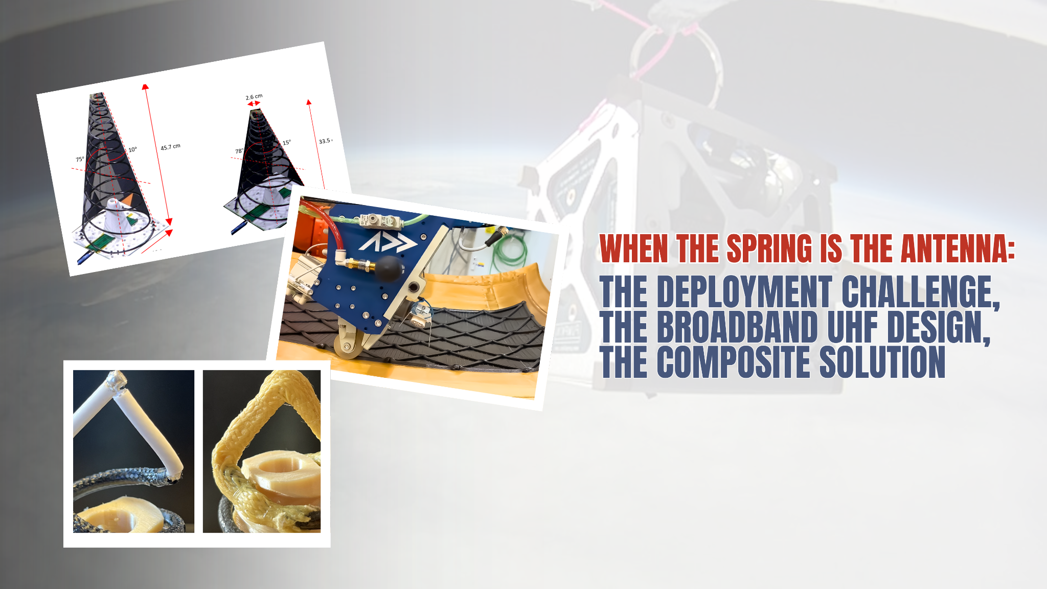
A CFRP Spring That Is Both the Deployment Mechanism and the Antenna: The Small-Satellite Design That Deletes an Entire Subsystem
On most small satellites, an antenna is a passenger. It rides up folded against the bus, waits for a separate mechanism to push it out, relies on a separate feed cable to carry the signal, and depends on a separate ground plane to point the beam in the right direction. Each of those is a part. Each part has mass, a failure mode, and an assembly step.
A March 2025 open-access paper in Aerospace (MDPI) takes a different route. The authors built a UHF antenna where the part that springs the antenna open and the part that radiates the signal are the same carbon-fiber-reinforced polymer (CFRP) structure. The spring is the antenna. There is no separate deployment boom, no cable run to the tip of the cone, and no purpose-sized ground plane.
For anyone working in composites for space hardware, this is a clean, fully-tested example of a trend worth paying attention to: the structural part and the functional component collapsing into one piece of CFRP.
A Note on Attribution
A note on attribution before we start. Everything described as the design, method, or result below comes from the cited paper by Williams and colleagues. Sections labeled "Our perspective" are commentary from Addcomposites and do not represent the views of the paper's authors, who have not reviewed, endorsed, or been involved with this article in any way.
The problem the authors set out to solve
The paper opens by surveying what already exists. According to the authors, the UHF antennas that have actually flown on small satellites tend to be narrowband types — dipoles, monopoles, Yagi-Uda, and helical designs. Broadband UHF antennas are attractive because a single satellite carrying one, paired with a software-defined radio, could cover several jobs at once: talking to Internet-of-Things sensors, taking radiometric measurements, handling communications. The catch is size. A broadband UHF antenna can be physically larger than the satellite itself, which forces a deployment mechanism, and every added mechanism adds complexity and risk.
The authors walk through a range of deployable broadband concepts from the literature — tightly coupled dipole arrays, several variants of the helix family, crossed log-periodic dipole arrays, and conical log spiral antennas. Their assessment is that, as far as they were aware, none of those concepts had yet been proven in actual spaceflight.
They zero in on the Conical Log Spiral Antenna (CLSA) because, in their account, it lands close to a crossed log-periodic array on performance while being easier to build mechanically. But a traditional CLSA has an awkward feeding problem. It is normally fed at the apex (the narrow tip), and it radiates back toward that feed point. On a satellite, feeding the tip means running a transmission line all the way from the bus up to the top of a deployed structure — more deployable hardware. The alternative, feeding it at the base, normally requires a ground plane sized roughly as large as the antenna is tall, to bounce the signal away from the spacecraft. On a small bus, that plane may not fit, so it too might need to deploy.
Conventional small-satellite antennas split their job across many separate parts — a deployment boom, hinges, a release latch, a feed cable, a connector, and often a ground plane. Each one adds mass, an assembly step, and a potential failure point. (AI-generated illustration)
So the design goal, as stated by the authors, was to get rid of both headaches at once: the antenna should need neither a fold-out cable reaching the cone tip nor a ground plane cut to a particular size.
One structure, several jobs
The authors' solution is to make the radiating element out of coaxial cable, embed that cable inside a carbon-fiber spring, and use a feeding trick called an infinite balun so the whole thing can be fed at the base while still radiating toward the apex — with no ground plane required.
The result is a single CFRP structure doing the work that is conventionally split across several separate parts. The diagram below maps the conventional split against the integrated approach described in the paper.
Conventional Deployable UHF Antenna vs. Integrated CLSA
Four discrete components merged into a single carbon-fiber composite spring
(functions handled by separate parts)
(functions in one CFRP spring)
- springs open on orbit
- is the structure
- houses the radiator (embedded coax)
- fed at the base
- no ground plane
The carbon composite supplies the spring behavior that opens the antenna on orbit. The coaxial cable threaded through it is simultaneously the radiating element and the balun. And because of how that balun is arranged, the electrical feed point sits at the base even though, electrically, the two halves of the antenna meet at the apex.
Two designs, dialed in by cone angle
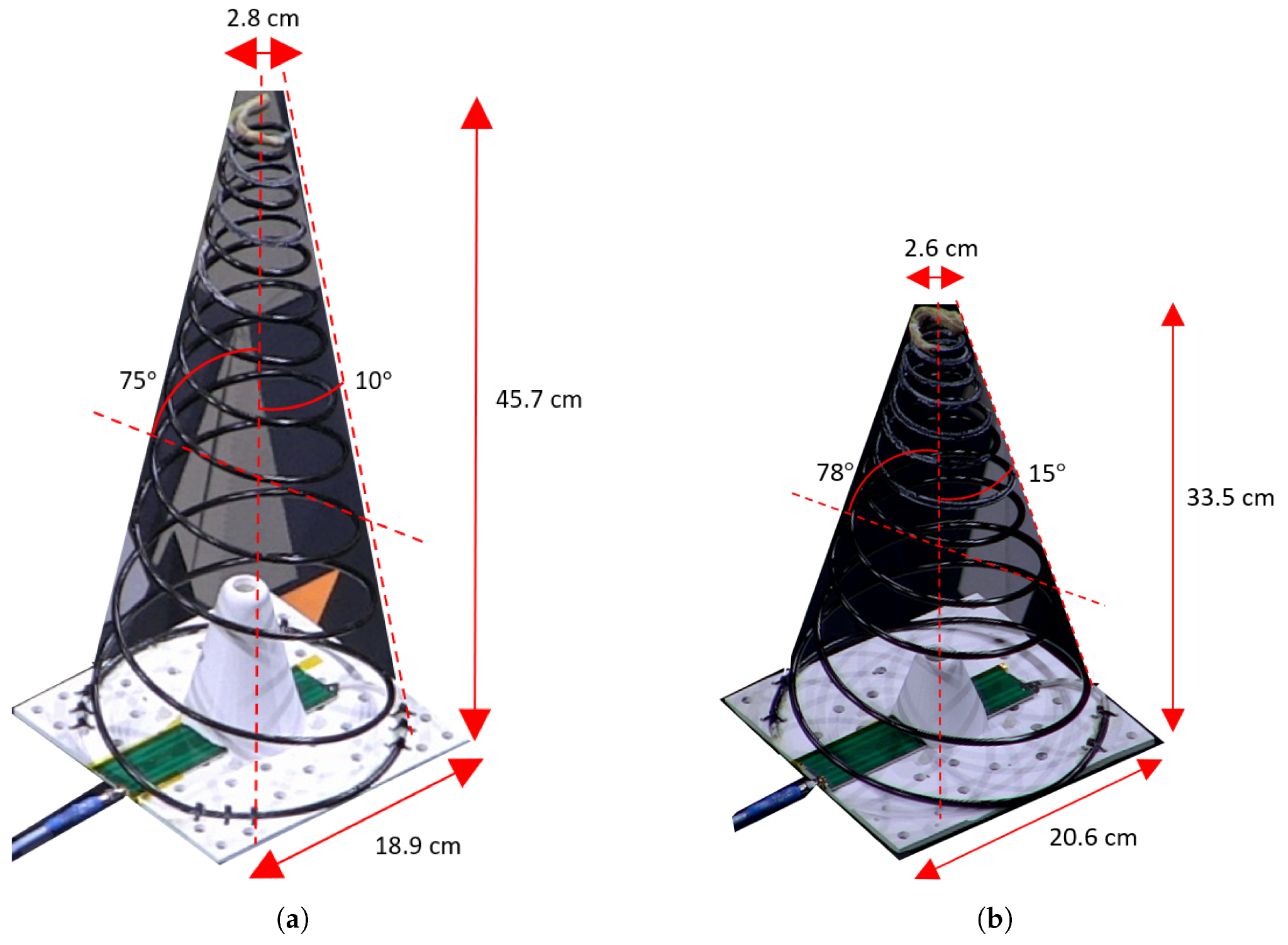
Side-by-side renders of the two 500–1500 MHz designs mounted on their square base plates: (a) the "long" design with a 10° cone angle, 75° wrap angle, 2.8 cm top diameter, and 45.7 cm height; (b) the "short" design with a 15° cone angle, 78° wrap angle, 2.6 cm top diameter, and 33.5 cm height. Figure 1 from: Williams, L.R.; Hoel, K.V.; Bråten, L.E.; Romeijer, A.; Hjermann, N.; Sagsveen, B. "A Deployable Conical Log Spiral Antenna for Small Spacecraft: Electronic Design and Test." Aerospace 2025, 12, 218. https://doi.org/10.3390/aerospace12030218 — © 2025 by the authors. Licensed under CC BY 4.0 (https://creativecommons.org/licenses/by/4.0/).
The authors built and tested two versions, both covering 500 to 1500 MHz and both right-hand circularly polarized. They are structurally similar but differ mainly in cone angle, which trades RF performance against physical size and stiffness.
The "long" design uses a 10° cone angle and a 75° wrap angle. The "short" design uses a 15° cone angle and a 78° wrap angle. The authors note that narrowing the cone angle should sharpen the RF behavior, but it pays for that with extra height and a spring that resists compression more. Each antenna is made of a pair of matching conical spirals set half a turn (180°) apart, and both sit on a 20 cm × 20 cm square base plate.
The figure shows both prototypes as built, with the cone angles, wrap angles, and overall dimensions marked by the authors.
CLSA Geometry: Long Design vs. Short Design
Trade-offs in spring angle, height, base width, and RF performance
- taller, stiffer
- longer coax run (215 cm)
- better directivity / F-to-B
- shorter, softer
- shorter coax run (190 cm)
- easier to compress
Feeding it without a ground plane: the infinite balun
This is the electrical heart of the design. The authors use a feeding arrangement, originally introduced by Dyson, called an infinite balun, in which the coaxial cable itself serves as both the feed and the radiating conductor.
Here is how the paper describes the current path. The drive current enters the coaxial cable of the first spiral arm down at the base of the cone and travels up to the tip. There the cable ends, and its center conductor jumps across to drive the braid of the second arm. That second arm is built from the same kind of coaxial cable, used to keep the two arms symmetric. Current then flows back down along the outside of the second arm's braid, and where that arm reaches the base the cable simply terminates open.
CLSA Bifilar Feed: How Current Travels
Inner conductor and outer shield carry opposing currents up opposite spirals — they meet and bridge at the apex
The clever part, from a systems point of view, is the consequence of all this. The authors point out that although, in strict electrical terms, the drive point lives at the cone tip where the two arms join, embedding the cable in the structure means the actual feed network and connection sit down at the base. That is exactly what lets the antenna be fed at the bottom while still radiating toward the top — and it removes the need to run any cable up to the apex after deployment.
For a balanced feed, the current arriving from the apex has to fade away to almost nothing before it reaches that open base of spiral two. As we will see in the results, the shorter design does not quite give the current enough length to decay, which shows up in its radiation pattern.
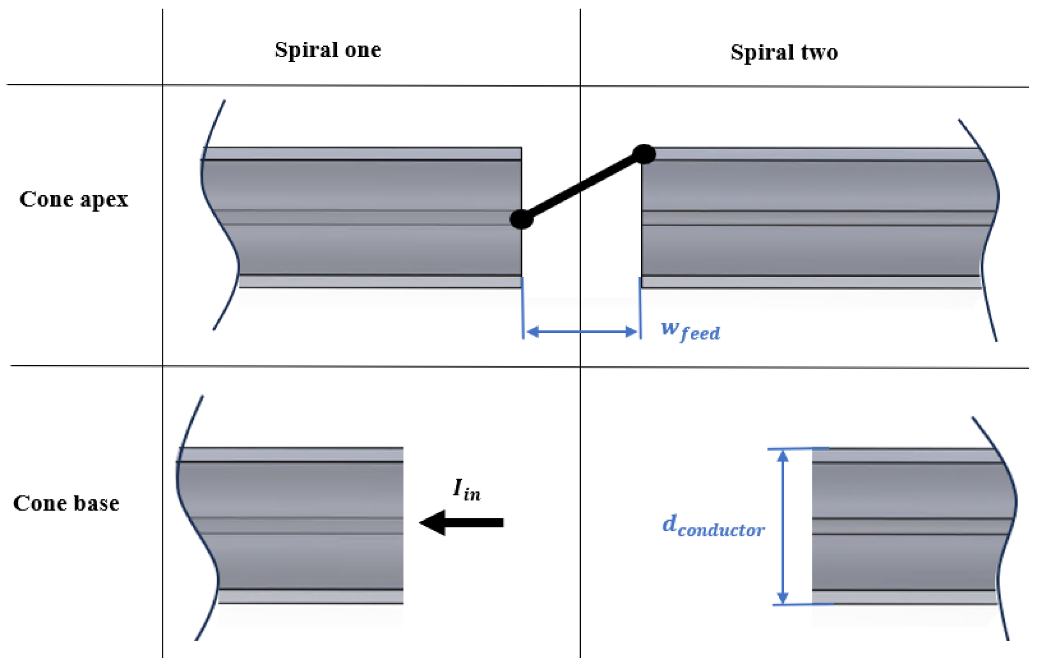
The schematic traces the current path through the two coaxial spiral arms: drive current (I_in) enters spiral one at the cone base, travels to the apex, and the inner conductor bridges across to feed the shield of spiral two, with the feed gap (w_feed) and conductor diameter marked. Figure 2 from: Williams, L.R.; Hoel, K.V.; Bråten, L.E.; Romeijer, A.; Hjermann, N.; Sagsveen, B. "A Deployable Conical Log Spiral Antenna for Small Spacecraft: Electronic Design and Test." Aerospace 2025, 12, 218. https://doi.org/10.3390/aerospace12030218 — © 2025 by the authors. Licensed under CC BY 4.0 (https://creativecommons.org/licenses/by/4.0/).
Matching the impedance: a four-stage Chebyshev transformer
A conical log spiral does not present a single clean impedance across its whole band. Drawing on Dyson's earlier measurements, the authors take the antenna's characteristic impedance to fall somewhere between roughly 80 and 320 Ω, with the conductor diameter being the main lever for controlling it — a fatter conductor pushes the impedance down.
They chose to feed the structure with 95 Ω coaxial cable. The appeal was practical: the value falls inside that 80–320 Ω workable band, the cable is readily available off the shelf, and its body is wider than a 50 Ω cable, which is an advantage here. To get from a standard 50 Ω source up to 95 Ω, they designed a four-stage Chebyshev transformer printed on Rogers 4350B substrate.
Stepped Impedance Transformer: 50 Ω → 95 Ω
Four quarter-wave stages widen the microstrip trace to match the source to the coax feed
The authors report that, across the design band, the transformer's S11 stayed under −15 dB, with insertion loss (S12) sitting around 0.1 to 0.25 dB. They describe it as good enough for prototype testing and note it could be improved with a longer transformer carrying more stages.
For the spiral arms themselves, the prototypes used Huber+Suhner RG195 A/U coaxial cable with the outer jacket stripped off. The authors are candid about the trade-off here: the RG195 jacket material is not especially radiation-resistant, and its specified maximum operating frequency is only 1 GHz. They tested the cable up to 6 GHz on a network analyzer and found it worked fine across their band, and they note that the closely related RG180 cable — with a jacket better suited to space — would be the flight choice, but it was skipped here because of longer lead time.
Inside the wall: what the structure is made of
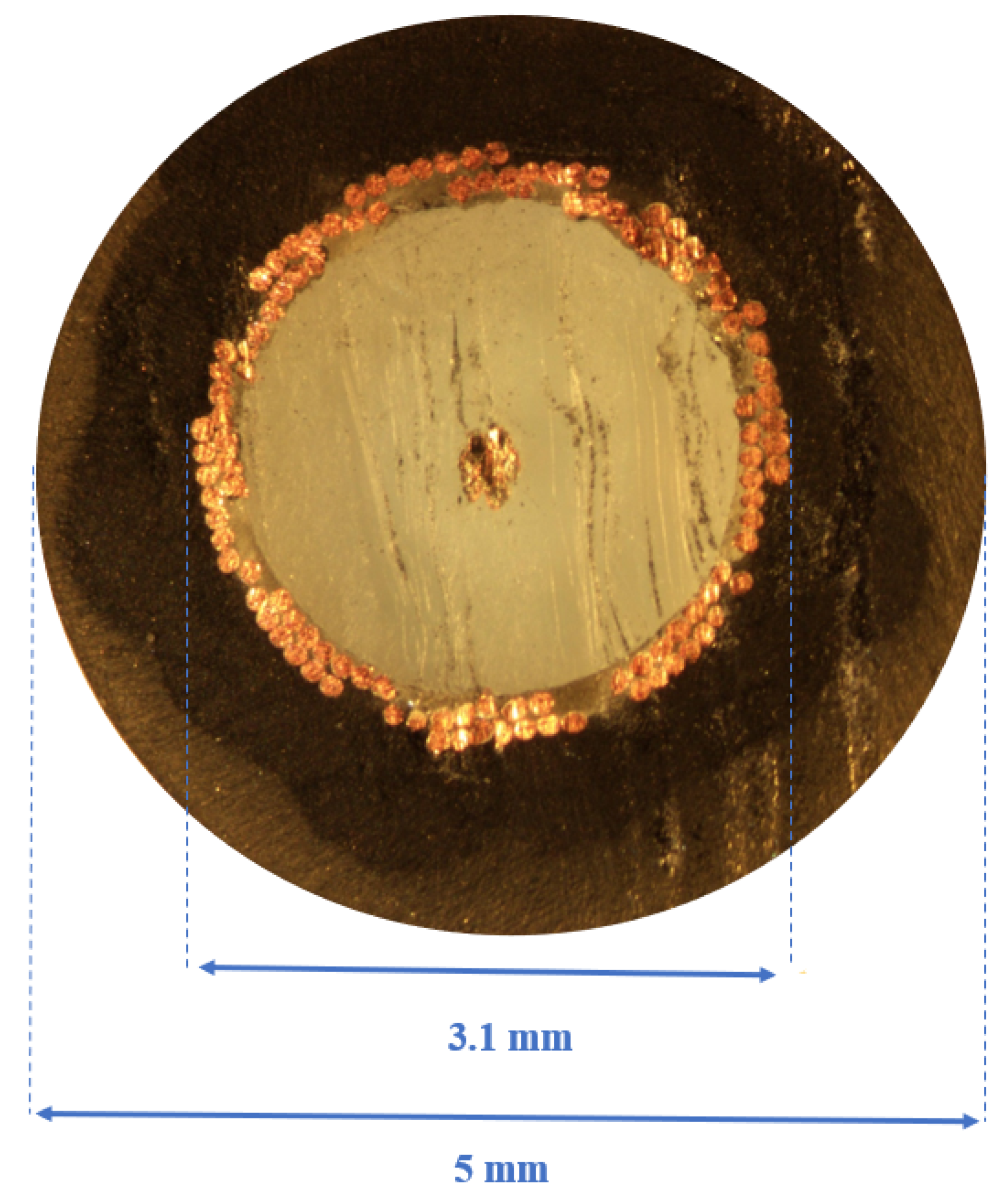
A cross-section cut through one spiral arm shows the stripped RG195 coaxial cable sitting inside the carbon-fiber epoxy composite, with the inner feature measuring roughly 3.1 mm and the outer wall about 5 mm across. Figure 5 from: Williams, L.R.; Hoel, K.V.; Bråten, L.E.; Romeijer, A.; Hjermann, N.; Sagsveen, B. "A Deployable Conical Log Spiral Antenna for Small Spacecraft: Electronic Design and Test." Aerospace 2025, 12, 218. https://doi.org/10.3390/aerospace12030218 — © 2025 by the authors. Licensed under CC BY 4.0 (https://creativecommons.org/licenses/by/4.0/).
The antenna wall is a carbon-fiber epoxy composite that physically contains the coaxial radiator and behaves as a spring. The authors built it from a braided carbon-fiber tube (Dowaksa A38 3K braid) infused with a SikaBiresin epoxy system. A cross-section through the wall shows the stripped coaxial cable sitting inside the composite.
A cross-section cut through one spiral arm shows the stripped RG195 coaxial cable sitting inside the carbon-fiber epoxy composite, with the inner feature measuring roughly 3.1 mm and the outer wall about 5 mm across. Figure 5 from: Williams, L.R.; Hoel, K.V.; Bråten, L.E.; Romeijer, A.; Hjermann, N.; Sagsveen, B. "A Deployable Conical Log Spiral Antenna for Small Spacecraft: Electronic Design and Test." Aerospace 2025, 12, 218.
At the apex, the two spiral arms are soldered together, with the feed gap squeezed to below a millimeter. That joint is wrapped in a Kevlar-braided tube and epoxy. The authors picked Kevlar rather than carbon fiber there precisely because it does not conduct: the reinforcement has to keep the two arms electrically separated while still stiffening and protecting the joint. To close out the build, that lower spiral-one end is joined straight to the transformer board, and a structural epoxy adhesive is added at the solder points for extra protection.
Cross-Section Through One Spiral Arm
The composite wall provides the spring force; the embedded coax does the radiating (not to scale)
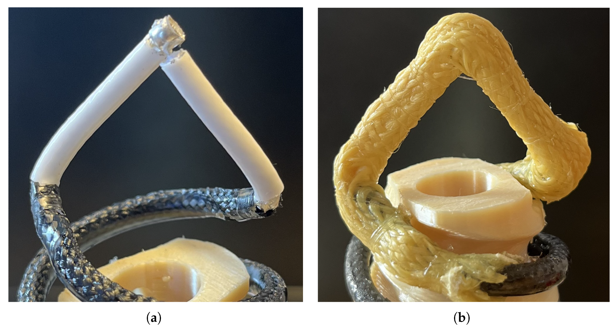
(a) shows the two coaxial spiral arms soldered together at the apex of the cone, where the feed gap is squeezed to below a millimeter; (b) shows that solder joint wrapped in a Kevlar-braided tube and epoxy, used in place of carbon fiber so the reinforcement stiffens and protects the joint without electrically connecting the two arms. Figure 6 from: Williams, L.R.; Hoel, K.V.; Bråten, L.E.; Romeijer, A.; Hjermann, N.; Sagsveen, B. "A Deployable Conical Log Spiral Antenna for Small Spacecraft: Electronic Design and Test." Aerospace 2025, 12, 218. https://doi.org/10.3390/aerospace12030218 — © 2025 by the authors. Licensed under CC BY 4.0 (https://creativecommons.org/licenses/by/4.0/).
The authors note that the full mechanical story — how the part is made and how it holds up to environmental testing — is covered in a separate companion paper; this one stays on the electronic design and RF testing.
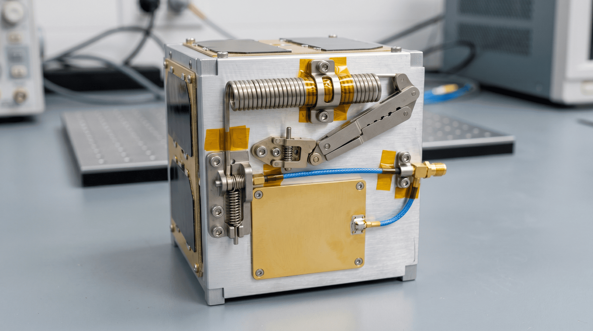
Surviving deployment: what 200 compressions did
A deployable spring antenna has to be squashed flat for launch and then released. The authors describe holding the compressed spring down with a burn-wire device; once on orbit, the wire is cut and the antenna extends to its working length. A non-conductive standoff keeps the antenna off the (prototype) PLA base plate electrically.
Composite springs settle a little the first few times they are compressed, so the authors deliberately cycled the antennas and tracked what happened. They 3D-scanned the long antenna before and after 200 compressions and measured a permanent shortening from about 45.7 cm to 44.4 cm, with the change concentrated toward the stiffer apex end.
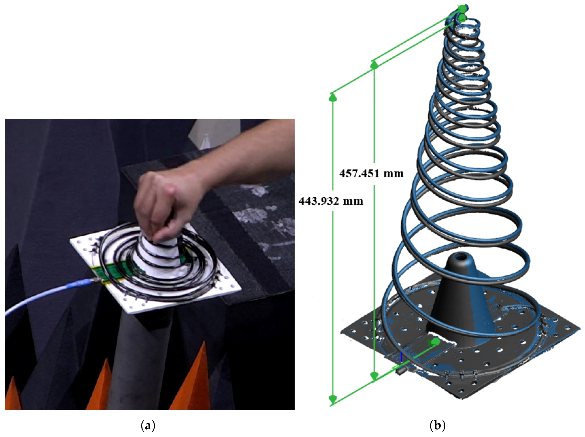
(a) shows the long antenna (α = 10°) physically compressed for stowage; (b) overlays 3D-scan geometry before and after 200 compressions, capturing the permanent shortening from about 457.5 mm to 443.9 mm, concentrated toward the stiffer apex. Figure 7 from: Williams, L.R.; Hoel, K.V.; Bråten, L.E.; Romeijer, A.; Hjermann, N.; Sagsveen, B. "A Deployable Conical Log Spiral Antenna for Small Spacecraft: Electronic Design and Test." Aerospace 2025, 12, 218. https://doi.org/10.3390/aerospace12030218 — © 2025 by the authors. Licensed under CC BY 4.0 (https://creativecommons.org/licenses/by/4.0/).
Long Antenna Height After Repeated Compression
3D-scan result comparing height before and after cycling
The reassuring finding, according to the authors, is that this geometric settling barely touched the electrical performance. They measured the antennas before compression and again after 10, 20, 50, 100, and 200 cycles, and report that the effect on both directivity and reflection coefficient was negligible. From that point on, they only present the post-200-compression data, on the logic that any real flight unit will have been cycled many times during testing.
How it actually performed
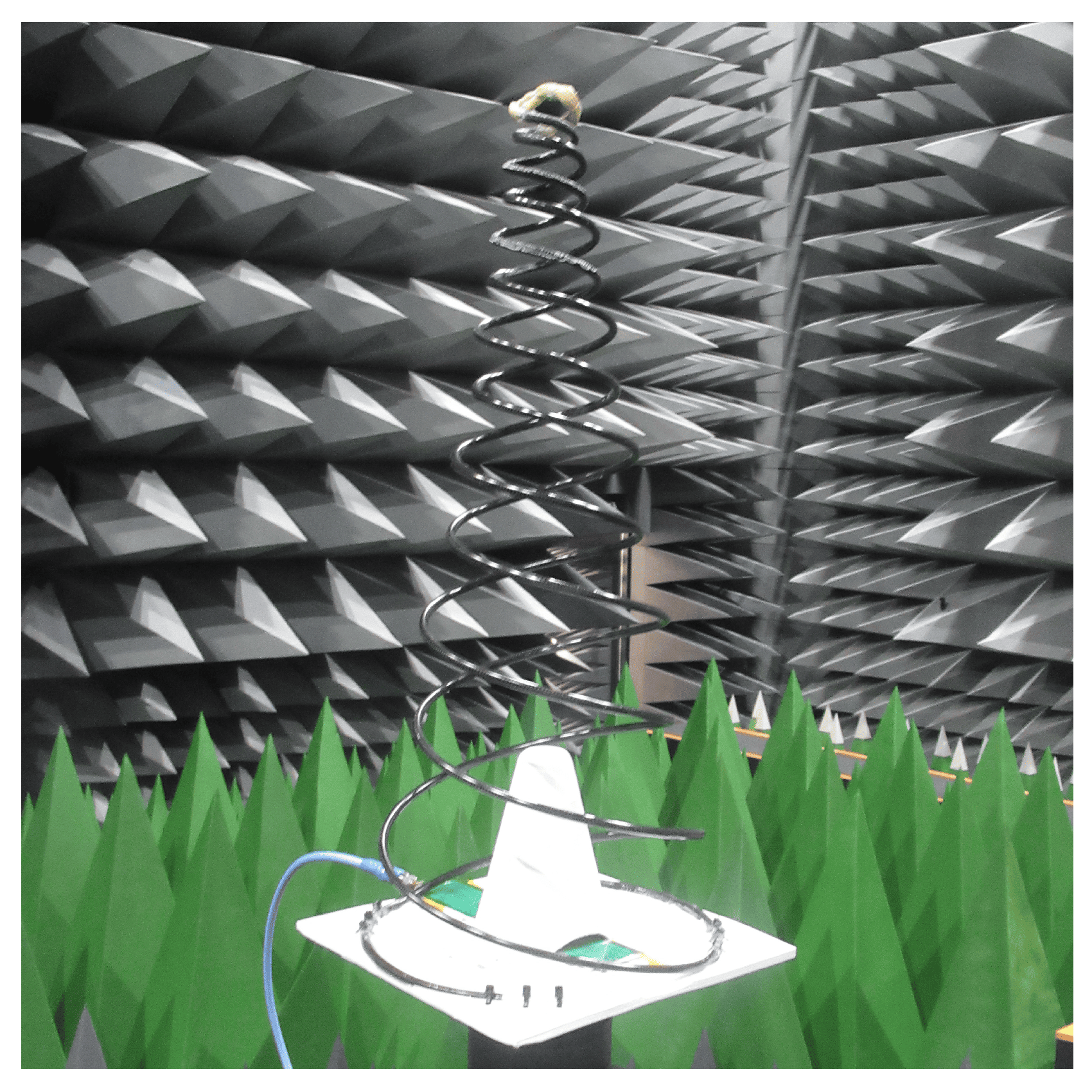
The deployed conical spring antenna hangs from its apex above its square base plate, with the blue coaxial feed cable attached at the base, inside the anechoic chamber. It is surrounded by pyramidal RF absorbers — dark grey on the walls and bright green in the foreground — that suppress reflections during the directivity, efficiency, axial ratio, and radiation pattern measurements. Figure 8 from: Williams, L.R.; Hoel, K.V.; Bråten, L.E.; Romeijer, A.; Hjermann, N.; Sagsveen, B. "A Deployable Conical Log Spiral Antenna for Small Spacecraft: Electronic Design and Test." Aerospace 2025, 12, 218. https://doi.org/10.3390/aerospace12030218 — © 2025 by the authors. Licensed under CC BY 4.0 (https://creativecommons.org/licenses/by/4.0/).
The antennas were characterized thoroughly. For S11, the team probed the transformer's input port with a Rohde & Schwarz vector network analyzer, while directivity, efficiency, axial ratio, and radiation patterns were measured by Pulsaart by AGC Glass Europe on a multi-probe spherical near-field range in Belgium, with simulations run in Ansys HFSS. The authors note the test facility is certified to ISO 17025:2017.
A few headline results, all as reported by the authors:
Directivity. The long design held a higher and flatter directivity across the band, hovering near 8.5 dBi toward the edges and easing to about 7 dBi through the middle; the short design dropped a little further, down to roughly 6 dBi. The simulations tracked the measurements well.
Efficiency and realized gain. The long antenna's extra length means a longer internal coax run and slightly more loss, which eats into its directivity advantage. The net effect is that, in terms of realized gain, the two designs end up performing similarly across the band.
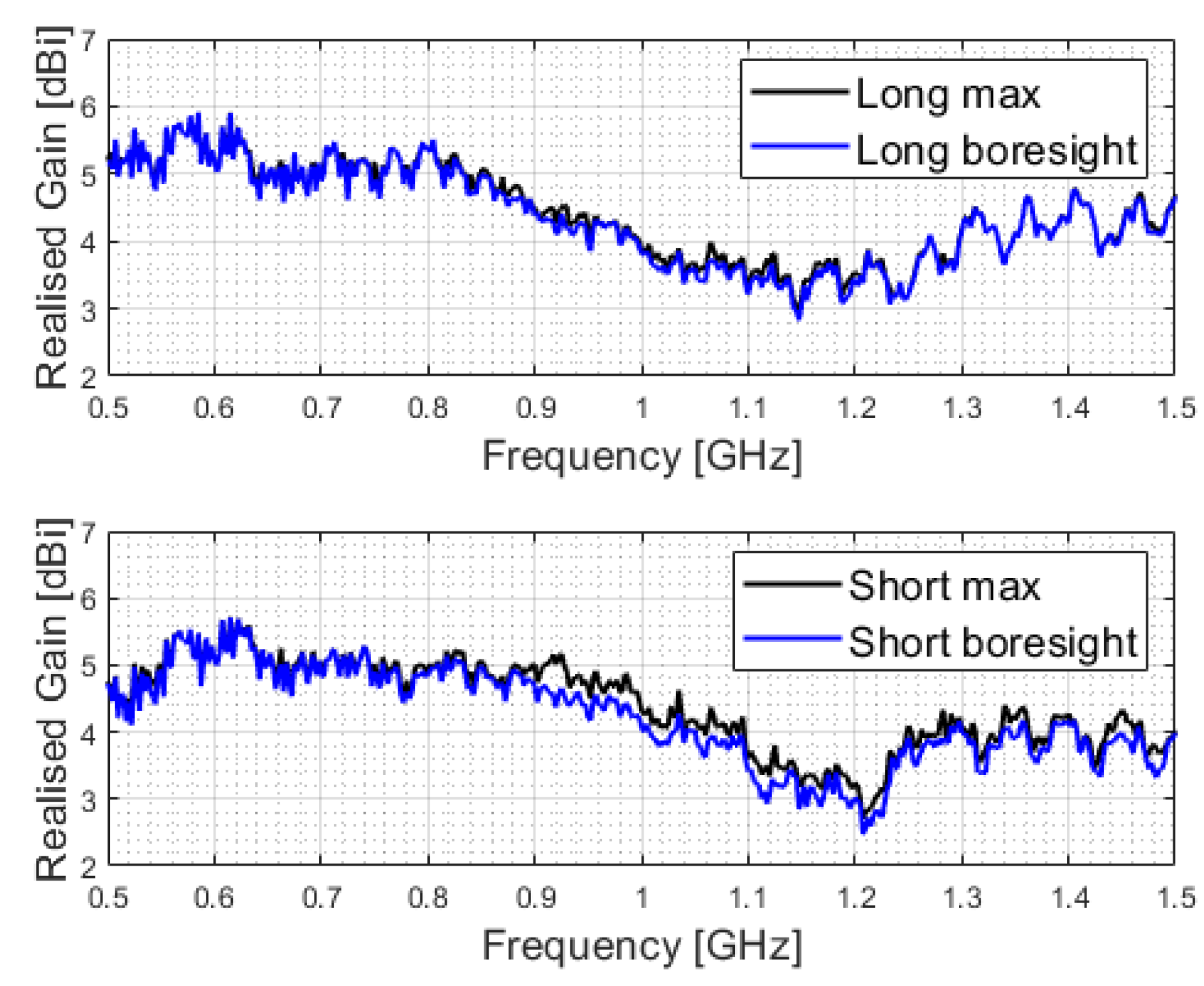
Two stacked plots show measured realized gain in dBi versus frequency from 500 to 1500 MHz, with both maximum and boresight traces given for the long antenna (top) and the short antenna (bottom). The gain sits roughly in the 3 to 6 dBi range across the band, and the maximum value does not always fall exactly at boresight. Figure 13 from: Williams, L.R.; Hoel, K.V.; Bråten, L.E.; Romeijer, A.; Hjermann, N.; Sagsveen, B. "A Deployable Conical Log Spiral Antenna for Small Spacecraft: Electronic Design and Test." Aerospace 2025, 12, 218. https://doi.org/10.3390/aerospace12030218 — © 2025 by the authors. Licensed under CC BY 4.0 (https://creativecommons.org/licenses/by/4.0/).
Polarization. Both antennas held an axial ratio below 3 dB — the usual mark of clean circular polarization — both at boresight and within ±30° of it.
The short design's tilt. Here is where the balun length matters. The authors observed that the short antenna's radiation pattern was slightly tilted, in both simulation and measurement. Their explanation: the shorter structure does not give the residual current enough distance to decay before it reaches the open base, leaving the feed slightly unbalanced. The long antenna, with more length, stayed properly balanced and showed essentially no tilt.
No ground plane needed — checked. Because the whole point was to avoid a sized ground plane, the authors simulated the long antenna sitting 3 mm above a 20 cm × 20 cm aluminum plate (the footprint of the prototype) to mimic a spacecraft surface. Across most of the band the plate barely changed the patterns; the one exception was the bottom of the band, at 500 MHz, where some distortion crept in — consistent, they note, with Dyson's much earlier observation.
Realized Gain Across the Band
Approximate envelope for both designs, 500–1500 MHz
The authors also mention that the University of Oslo lodged an initial patent filing covering the work in March 2025, and that the project was funded by the Research Council of Norway through the Centre for Space Sensors and Systems.
Our perspective: this is multifunctional CFRP, fully tested
The following is commentary from Addcomposites. It is our own analysis and is not drawn from, or endorsed by, the paper's authors.
What makes this paper worth a composites manufacturer's attention is not the antenna specialism — it is the design philosophy underneath it. The team didn't bolt a radiator onto a structure. They made one CFRP part carry the structural load, provide the deployment spring force, and host the radiating element, and then they verified that all three jobs survive together through 200 deployment cycles and a full RF characterization campaign.
That is the direction small-satellite structures are heading. In a sector where the design driver is mass and part count per function, the most valuable composite part is increasingly the one that stops being "a structure that holds other components" and becomes "the component." Every subsystem that folds into the primary structure is mass removed, an interface deleted, and a failure mode retired.
It is worth being precise about how this specific prototype was built: the authors used a braided carbon-fiber tube infused with epoxy, not automated fiber placement. So this is not a story about how the part was manufactured — it is a demonstration that a multifunctional CFRP part of this kind works.
Where we think the manufacturing question gets interesting is in what comes next for parts like these. The spring behavior here is governed by the composite's stiffness, which in turn depends on fiber orientation, fiber volume fraction, and local laminate architecture. Those are exactly the variables that automated fiber placement is built to control precisely and repeatably. As multifunctional CFRP parts move from one-off research prototypes toward small-series production — satellite bus panels, structural tubes, brackets, and integrated structures where the part has to hit a mechanical spec and a second functional spec at once — the ability to place fiber deterministically becomes a way to tune both behaviors at the same time.
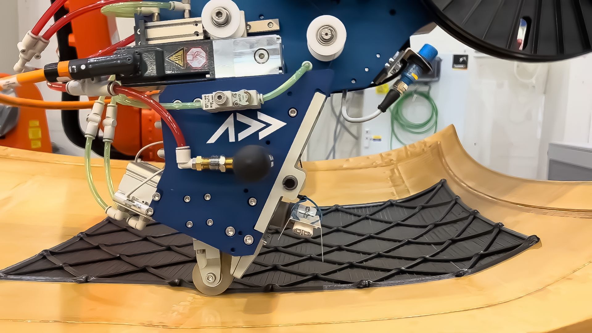
An Addcomposites AFP-XS head lays carbon fiber tow along defined paths on a curved mould. Fiber orientation, coverage, and architecture are all set in the toolpath, the same deterministic control the deck research depends on.
That is the bet behind tools like the AFP-XS and the ADDX platform: giving teams accessible, programmable control over the laminate so that "the structure is the component" parts can be designed, iterated, and produced without a heavy industrial footprint. This paper is a clean, peer-reviewed proof point that the underlying idea — one CFRP structure, several jobs — is not just plausible but testable and mission-relevant.
If you are working on integrated or multifunctional composite structures for space hardware and want to talk through how fiber placement could help you hit two specs in one part, we would like to hear what you are building.
Contact Us for a ConsultationLearn More
Read the Research
- Williams, L.R.; Hoel, K.V.; Bråten, L.E.; Romeijer, A.; Hjermann, N.; Sagsveen, B. "A Deployable Conical Log Spiral Antenna for Small Spacecraft: Electronic Design and Test." Aerospace 2025, 12, 218. https://doi.org/10.3390/aerospace12030218
Published 7 March 2025 by MDPI. Open access under the Creative Commons Attribution (CC BY 4.0) license (https://creativecommons.org/licenses/by/4.0/).
All technical claims, figures, and results above are the work of the cited authors. Commentary attributed to Addcomposites is our own and does not represent the views of the authors or their institutions.
