AFP for CFRP Fan Blades: The 450% Efficiency Gain That Is Reshaping Aero-Engine Manufacturing
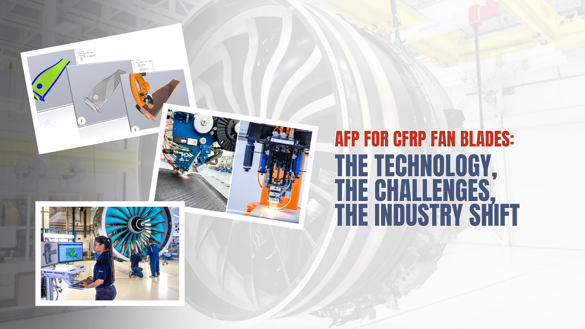
A landmark 2025 review in Composites Part A confirms what the industry has long suspected: Automated Fiber Placement is not merely a faster version of hand layup — it is the only viable manufacturing route to the next generation of high-bypass-ratio turbofan blades.
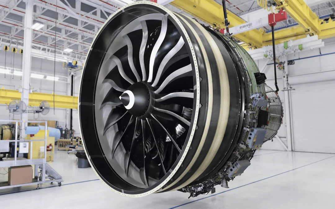
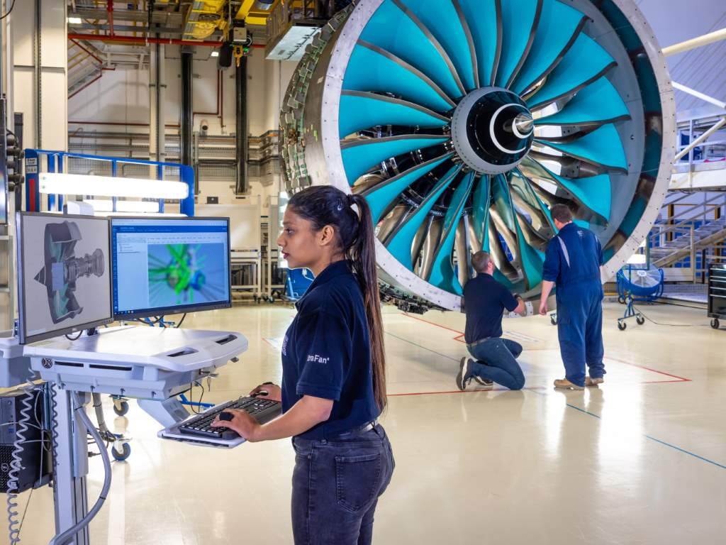
Somewhere in a test cell in Derby, a 140-inch fan — the largest ever built for a commercial aero-engine — is spinning carbon-fiber blades that took decades and several false starts to get right. The Rolls-Royce UltraFan demonstrator achieved 85,000 lb of thrust on 100% sustainable aviation fuel in late 2023. Every one of those composite fan blades was produced using Automated Fiber Placement. That is not a coincidence.
A comprehensive 2025 review published in Composites Part A: Applied Science and Manufacturing (Zhou et al., Beihang University) frames exactly why AFP occupies this position — and exactly where the remaining manufacturing science gaps are. The numbers it opens with are difficult to ignore: AFP has been demonstrated to enhance layup efficiency by up to 450%, reduce material waste by up to 6%, and facilitate a reduction in part manufacturing costs by up to 43% compared to the traditional hand layup method. This post unpacks what is behind those figures, what technical challenges remain, and what they mean for manufacturers evaluating AFP capability today.
Why Fan Blades Are the Hardest CFRP Problem in Aviation
To understand what AFP is being asked to solve, you first need to understand why fan blades are structurally and geometrically exceptional among composites applications.
A key driver for composites use has been the need to increase the engine bypass ratio (BPR). BPRs have increased from 5:1 in the 1970s to 10:1 for the LEAP engine and 15:1 for the Rolls-Royce UltraFan. A larger bypass ratio means a larger, slower fan moving more air around the engine core — which delivers better fuel efficiency and lower noise. The catch is that a larger fan demands larger, lighter blades, and larger blades subject to bird-strike, foreign object ingestion, and centrifugal loading in excess of anything titanium can cost-effectively absorb at that scale. Carbon fiber composites are the only material family that solves all three constraints simultaneously.
The evolution looks like this:
Bypass Ratio Evolution & Fan Blade Material Progression
BPR trend across engine generations — from titanium/metal blades to CFRP / AFP manufacturing
BPR = Bypass Ratio | CFRP = Carbon Fibre Reinforced Polymer | AFP = Automated Fibre Placement
A milestone in composite fan blade manufacturing was achieved with the series production of the GE90 engine. In the current era, composite fan blade production techniques have been applied to the GEnx and GE9X engines, CFM's LEAP-X, and Rolls-Royce's UltraFan. Each generation has pushed both material performance and manufacturing complexity higher. The GE90 blades used hand-laid IM7 carbon fiber/8551-7 epoxy prepreg — a process that was heroic at the time but is simply not scalable to the blade volumes and geometries now required. The GE9X employs a fourth-generation composite material comprising higher-strength carbon fibers and new high-toughness epoxy resin, and features an enhanced overall material strength allowing for a larger backward sweep, wider chord, and higher tip taper.
Wider chord, larger sweep, complex 3D twist — this is the geometry that has made hand layup untenable and automated processes mandatory.
AFP vs. The Alternatives: A Manufacturing Showdown
Three automated processes compete for rotary composite structure production: AFP, filament winding, and Resin Transfer Molding (RTM). Each has a legitimate claim in certain applications. For fan blades specifically, the field narrows considerably.
The key differentiator is fiber steering: AFP deposits narrow tows (typically 3.2–12.7 mm wide) along individually programmed trajectories, allowing fiber angles to vary continuously across a surface.
Manufacturing Process Capability Comparison for CFRP Fan Blades
Relative performance across seven criteria — lower waste and higher ratings indicate superior capability
| Criterion | Hand Layup |
Filament Winding |
RTM | AFP |
|---|
Filament winding excels on axisymmetric structures — pressure vessels, rocket motor cases, drive shafts. Fan blades, however, are not axisymmetric. They have spanwise twist, chord variation, a leading-edge geometry that changes radically from root to tip, and a requirement for precise off-axis fiber orientations throughout. Filament winding cannot deliver these without significant geometric compromise.
RTM (as used by CFM for LEAP-X blades) injects resin into a dry preform in a closed mold. It achieves excellent surface quality and is suitable for mid-complexity 3D shapes, but it requires separate preform manufacture, has limited fiber angle steering capability, and introduces process variability at the preform-to-mold interface. As blade geometries become more extreme — driven by higher BPR requirements — RTM's limitations in steering and preform handling become more constraining.
The high flexibility of AFP allowed for layup of increasingly complex parts, making AFP the potential technology to automate the CFRP fan blade. The key differentiator is fiber steering: AFP deposits narrow tows (typically 3.2–12.7 mm wide) along individually programmed trajectories, allowing fiber angles to vary continuously across a surface. This is what allows a manufacturer to chase the stress principal directions on a twisted, swept, variable-chord blade — placing material where it is structurally needed, in the orientation it needs.
The UltraFan Benchmark: Where Industry Is Already Committed
The most significant real-world proof point for AFP in fan blade manufacturing is the Rolls-Royce UltraFan program.
The Bristol composites facility dates back to Composite Technology and Applications Ltd (CTAL), a joint venture between Rolls-Royce and GKN Aerospace established in 2008. CTAL brought together Rolls-Royce's expertise in advanced engine technologies with GKN Aerospace's capabilities in composite research and automated manufacturing.
Rolls-Royce has re-launched the research of composite fan blade manufacturing technology by establishing a joint venture with GKN Aerospace, CTAL, with the objective of developing an AFP process for forming composite fan blades and fan case of the UltraFan engine. This new AFP technology developed by GKN has demonstrated the extremely high manufacturing flexibility and application potential in this field.
UltraFan Program Scale
As a set, the composite blades have a 140-inch diameter — almost the size of a current narrowbody fuselage — and are being made at the company's technology hub in Bristol, UK. Part of the efficiency improvement comes from UltraFan's composite fan blades and fan case, which reduce weight on a twin-engine aircraft by 700 kg, the equivalent of seven people travelling weight-free.
Phase two of UltraFan testing, which began in 2025, pushed the system further, testing cold weather performance, relight capability, altitude ground starting, combustor stability, and thermoacoustic performance, with over 25 flight tests and 14 ground tests completed.
This is not a research program. It is a production-intent development program, and AFP is at its manufacturing center.
The Three Open Technical Challenges (And Where Research Is Focused)
The Zhou et al. review is valuable not just for quantifying AFP's performance advantage but for its honest identification of what is not yet solved. Three challenges dominate the current research landscape.
AFP Fan Blade Manufacturing: Challenge Topology
Three converging challenge domains addressed by integrated R&D methodology
Geometry
Accuracy
Control
Challenge 1: Complex 3D Geometry
Fan blades are among the most geometrically demanding CFRP structures in aerospace. The surface is doubly curved with variable twist from root to tip, and the thickness distribution changes dramatically along both chord and span. Angular deviation of placed fibers compared to the CAD layup architecture must be no less than 5°, and the coverage ratio — the fraction of the surface covered by fiber as compared to gaps — must be maximized while defects caused by fiber steering are minimized. These boundary conditions are easy to state and extraordinarily difficult to achieve simultaneously on a fan blade geometry.
Challenge 2: Fiber Steering Accuracy
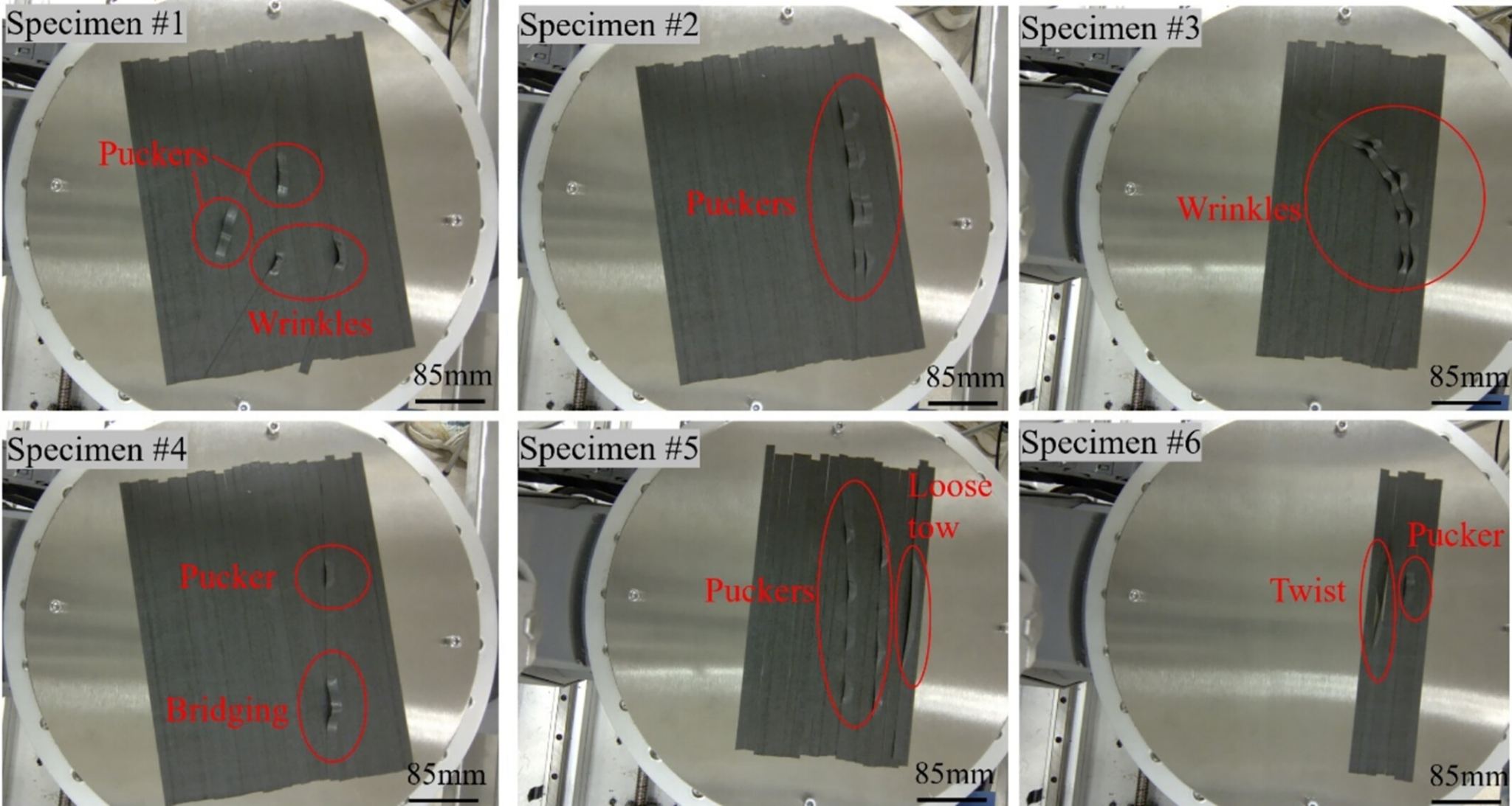
Steering tows using the AFP process introduces challenges in terms of quality and productivity due to steering-induced defects. The quality of AFP layup is highly dependent on the geometry and the curvature of the path, as well as the manufacturing process parameters such as layup temperature, head speed, and compaction force. On a flat panel, steering is manageable. On a blade with high leading-edge curvature and aggressive planform taper, the compressive stresses on the inner radius of a steered tow exceed the tow's ability to remain flat, producing wrinkles or puckers that cannot be tolerated in a rotating structure loaded in combined tension, bending, and torsion. Typical layup defects of AFP can be divided into in-plane defects (gaps or overlaps) and out-of-plane defects (including wrinkles, bridging, loose tows, and puckers).
Challenge 3: Process Window Control
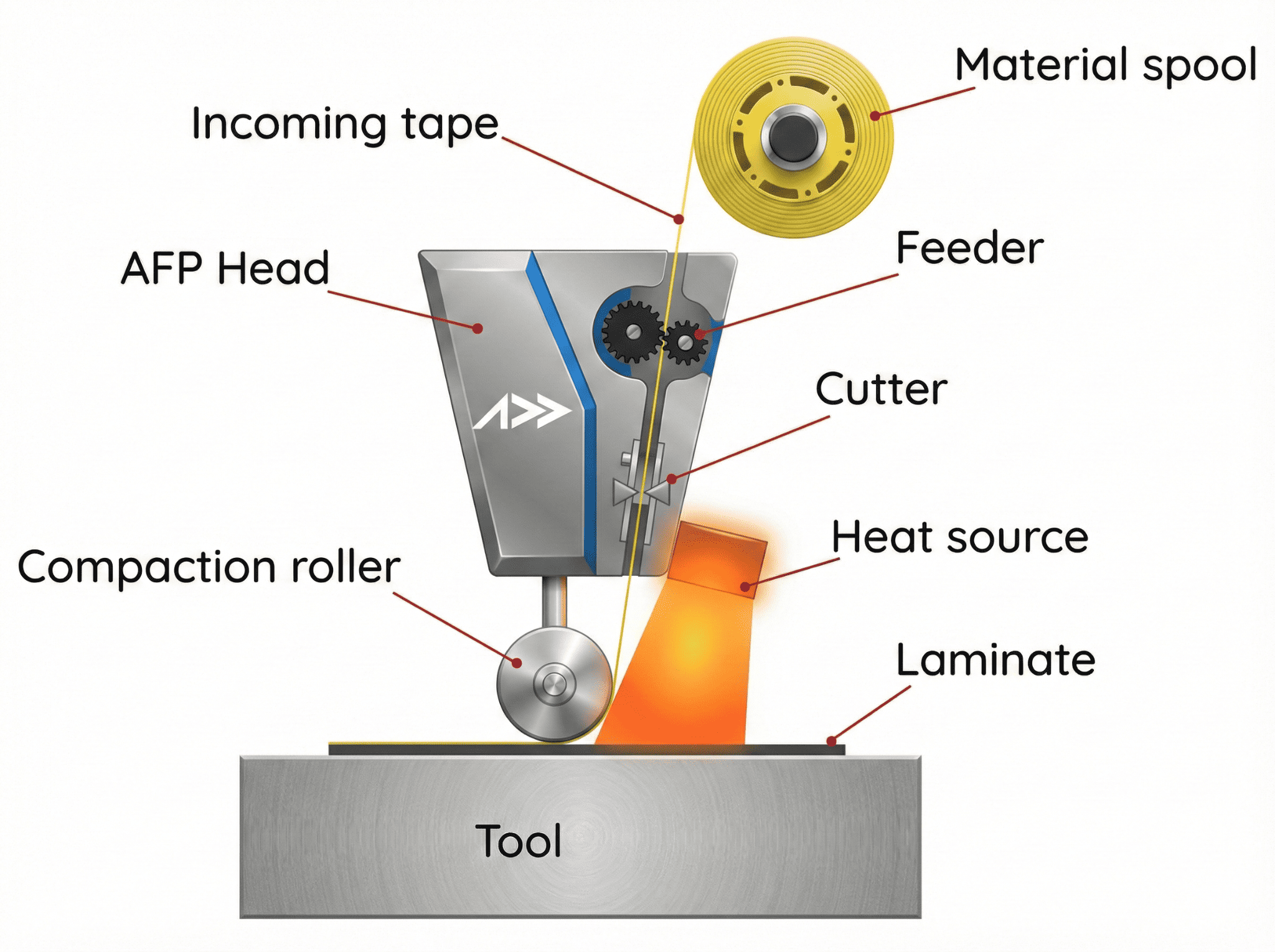
The AFP head must simultaneously manage heating temperature (for tack and/or in-situ consolidation), compaction force, and laydown speed — and these parameters interact nonlinearly. Too little heat and the tow does not bond; too much and the resin begins to cure prematurely or the thermoplastic overflows. Understanding how these parameters affect the process is important to achieve the desirable quality of the final part. For fan blade-class parts, where every ply contributes to FOD resistance and fatigue life, process window violations are not a rework issue — they are a rejection event.
The IRDM-AFP Framework: How the Research Gap Is Being Closed
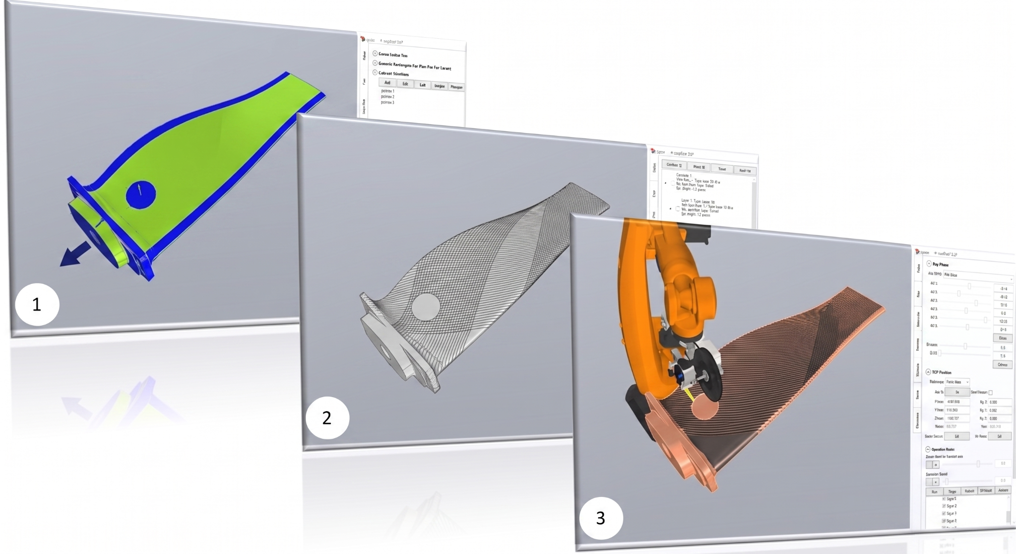
The 2025 Beihang review does more than describe the problems — it proposes an integrated methodology for solving them systematically. The Integrated Research and Development Method for AFP (IRDM-AFP) combines virtual and physical approaches in a closed loop aimed at simultaneous optimization of shape accuracy and mechanical performance.
IRDM-AFP: Integrated Development Loop
Virtual prediction and physical measurement converge iteratively to optimise blade shape accuracy and mechanical performance
The building-block verification approach embedded in IRDM-AFP — moving from element-level coupons to full blade — mirrors how aerospace structures qualification has always worked, but now with the closed digital loop making the progression faster and more information-rich than traditional empirical iteration. The 2025 review presents preliminary element-level AFP forming experiments as proof of concept for this methodology, demonstrating both its feasibility and the necessity of systematic integration between digital path planning and physical process feedback.
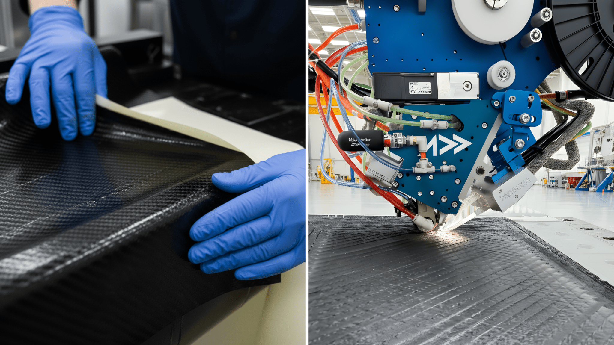
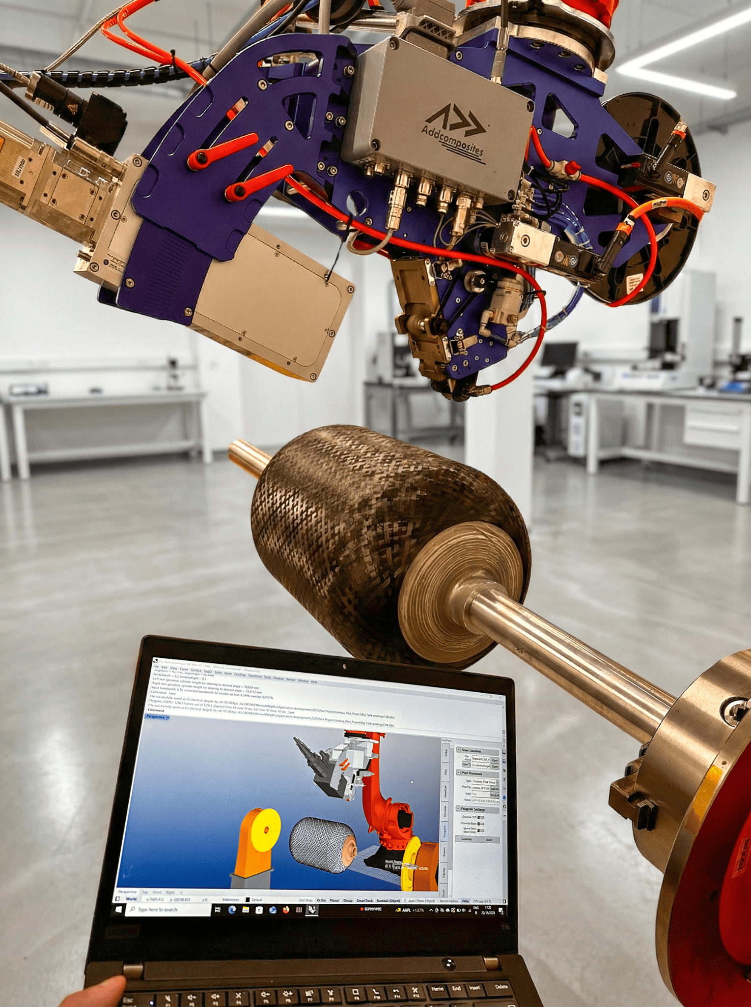
What This Means If You Are Running AFP-XS or AFP-X Today
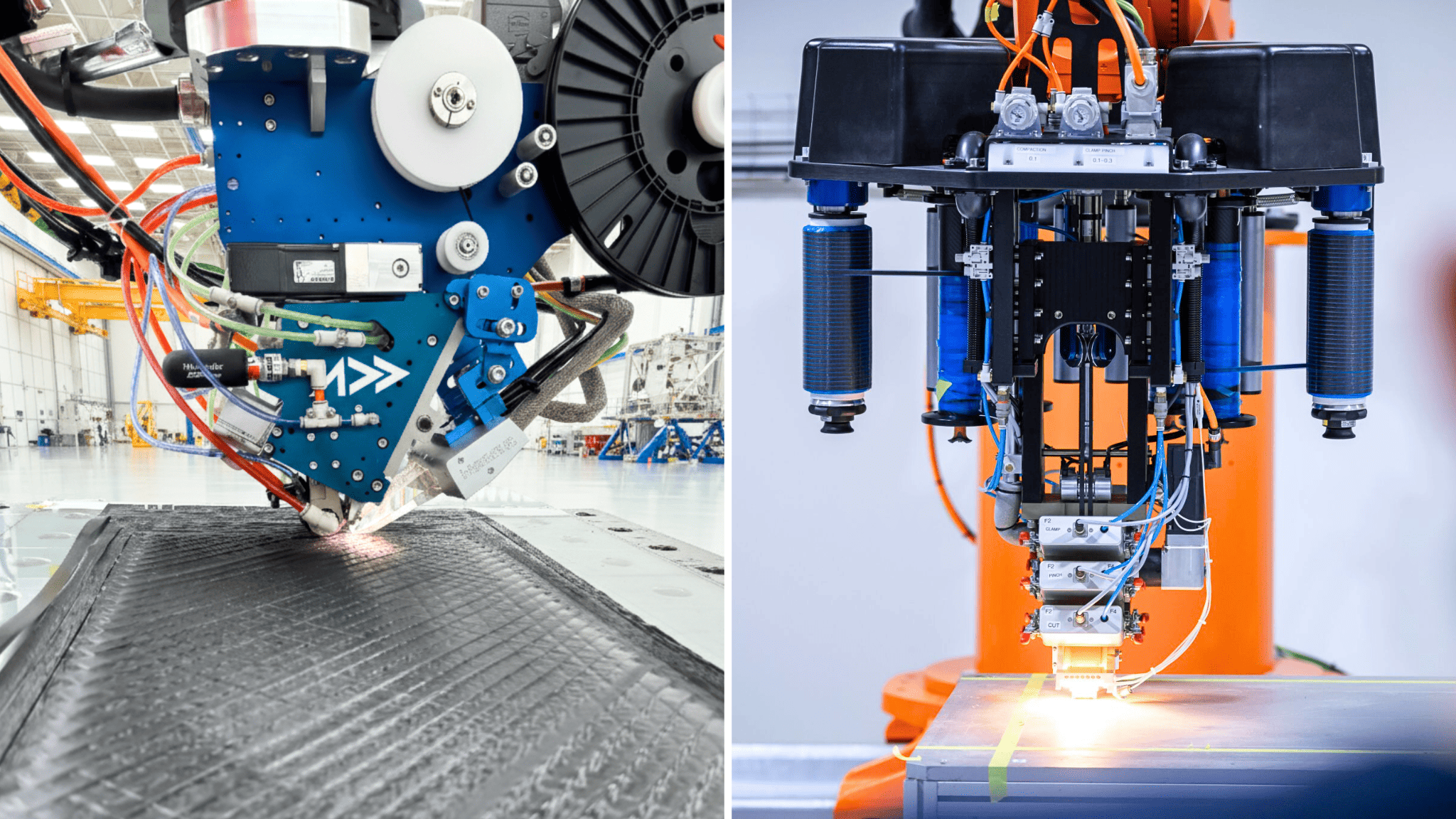
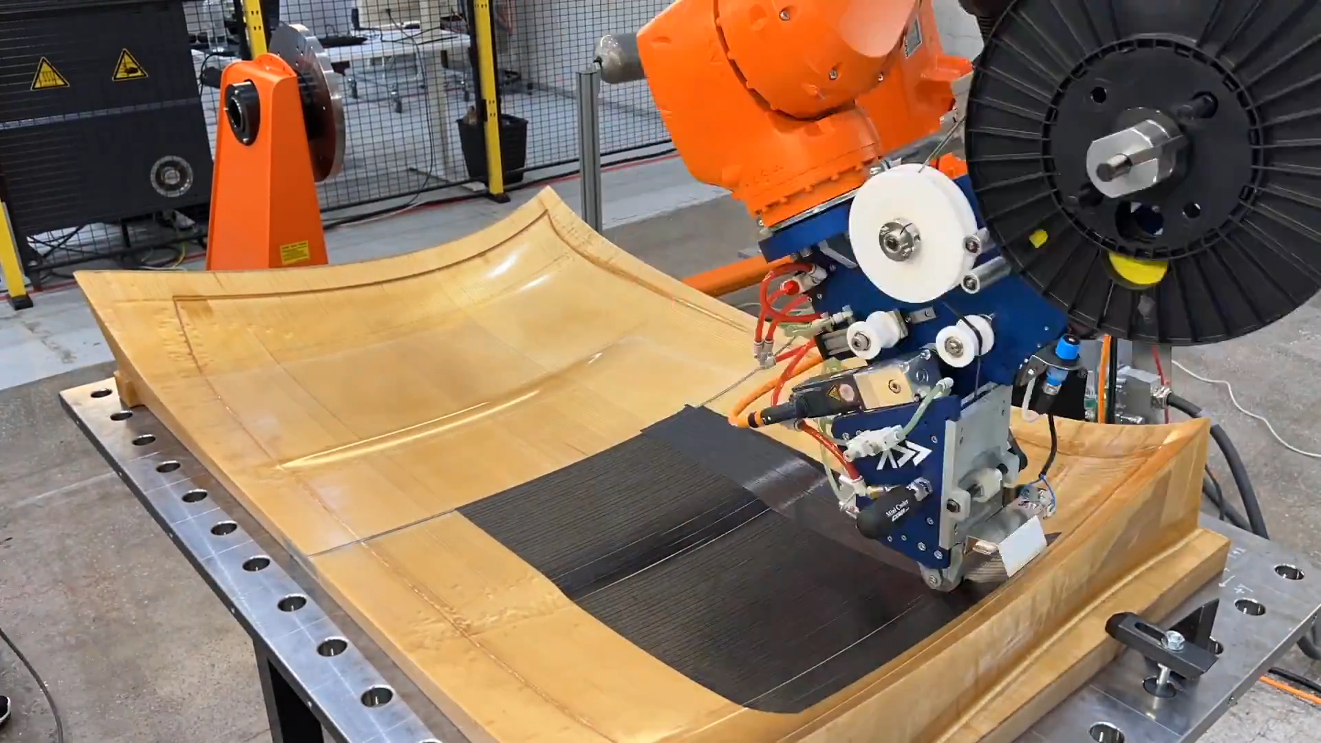
Addcomposites AFP-XS (left) and AFP-X (right) — laser-assisted fiber placement on production-grade surfaces, available on standard industrial robot arms.
The Composites Part A review frames AFP fan blade manufacturing as a solved-in-principle, unsolved-in-practice challenge — and that framing has direct implications for how AFP system users should position their capability.
Real Benchmarks, Not Claims
The 450% layup efficiency improvement, 6% material waste reduction, and 43% part manufacturing cost reduction against hand layup are documented figures from the production literature. They come from peer-reviewed manufacturing science, not vendor marketing.
Where Differentiation Happens
The technical challenges — steering-induced defects, compaction-temperature-speed coupling, coverage uniformity on double-curved surfaces — are precisely where the quality of the AFP head, the tow delivery system, and offline programming separates production-capable systems from those that can only lay flat panels.
Building-Block Methodology
IRDM-AFP's element → coupon → component → blade progression is directly supported by the parametric process simulation that AddPath enables. Running virtual layup simulations before cutting a single strip of prepreg is not a luxury — it is a qualification requirement.
Competitive Landscape Consolidating
The trajectory of increasing BPR, larger blade chord, and more aggressive 3D geometry is moving toward AFP's strengths and away from RTM's. Customers in UAM, defense rotorcraft, and next-generation narrow-body propulsion evaluating fan-class composite structures today will evaluate AFP as the enabling process.
The Convergence Point
The story told by Zhou et al. in Composites Part A is ultimately the story of an entire industry reaching a manufacturing inflection point. CFRP fan blades have been in service since the GE90 in the 1990s, but the process for making them has shifted from skilled-labor-intensive hand layup to automation-dependent AFP over thirty years of incremental technical development. The UltraFan program — with its 140-inch fan, AFP-manufactured CFRP blades, and 25% fuel burn improvement over first-generation Trent engines — is the clearest signal yet that this transition is complete for the leading edge of the industry.
What the 2025 review adds is a clear map of the science that remains to be done: complex geometry path planning, steering defect suppression, and closed-loop process window control. These are not theoretical obstacles. They are engineering problems with identified solution pathways — and the manufacturers and system providers who build deep competence in each of them will define who makes the fan blades of the 2030s.
The Strategic Question
For AFP system users in propulsion, defense, and advanced air mobility, the question is no longer whether AFP is the right process for fan blade-class CFRP structures. The question is whether your process chain — your path planning software, your head kinematics, your in-process monitoring, and your defect model — is ready to meet the geometry and quality requirements that the next generation of designs will demand.
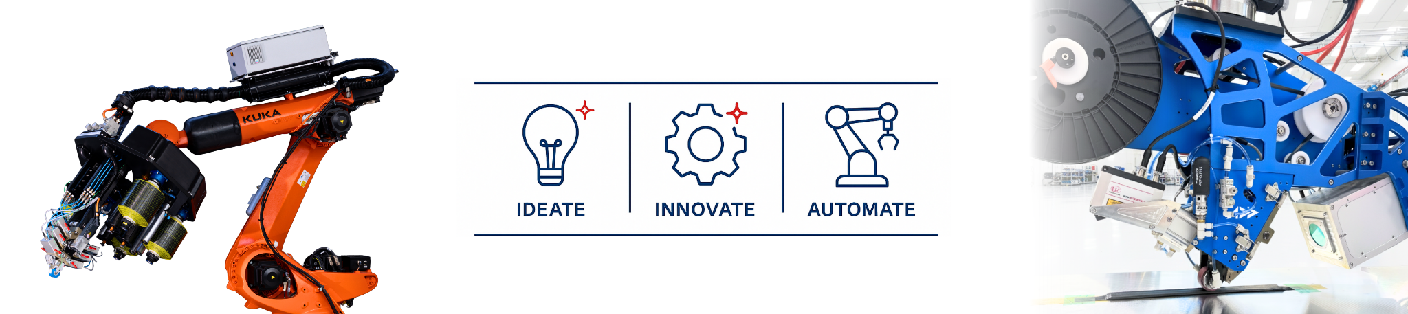
About Addcomposites
Addcomposites provides the AFP ecosystem for accessible, high-quality automated composite manufacturing — including the AFP-XS and AFP-X fiber placement systems, the AddPath 3D simulation and programming environment, and the AddCell robotic manufacturing cell. AFP-XS and AFP-X support thermoset, thermoplastic, and dry fiber placement on standard industrial robot arms from KUKA, ABB, Fanuc, and others, with a flexible lease model that makes fan-blade-class AFP capability accessible without eight-figure capital commitment.
To explore AFP for propulsion-class CFRP geometry, contact the Addcomposites team or download AddPath to run your first blade layup simulation.
Learn More
To explore AFP for propulsion-class CFRP geometry, contact the Addcomposites team or download AddPath to run your first blade layup simulation →
Contact Us for a ConsultationReferences
- Zhou, H., Li, X., Shao, C., Li, X., Li, Y.*, Li, D., Feng, J., Ding, X. and Zhu, Y. (2025). Review on the automated fiber placement process for the aero-engine composite fan blade and its feasibility in element level. Composites Part A: Applied Science and Manufacturing, p.108875. https://doi.org/10.1016/j.compositesa.2025.108875
- CompositesWorld; Rolls-Royce plc press releases; Wiley Polymer Composites (2025); ScienceDirect — Advances in resin matrix composite fan blades (2024).
