Bio-Inspired Joints from Beetle Armor Are Now Outperforming Riveted CFRP Connections
The Problem Nobody's Fixed Yet
Ask a structural engineer designing a CFRP airframe panel what they do at the joint to a metallic subframe, and the answer is usually some variant of: drill holes, insert fasteners, reinforce locally, and live with it.
Hole-drilling in carbon fiber reinforced polymers is one of the most reliably damaging manufacturing steps in composite assembly. Each drill creates a zone of delamination risk, severs fibers that were oriented to carry load, and introduces a stress concentration at precisely the location where load transfer is highest. Riveted and bolted CFRP connections are structurally effective enough that they remain standard practice — but they carry a hidden cost in production scrap, rework, and structural knockdown factors built into every margin calculation.
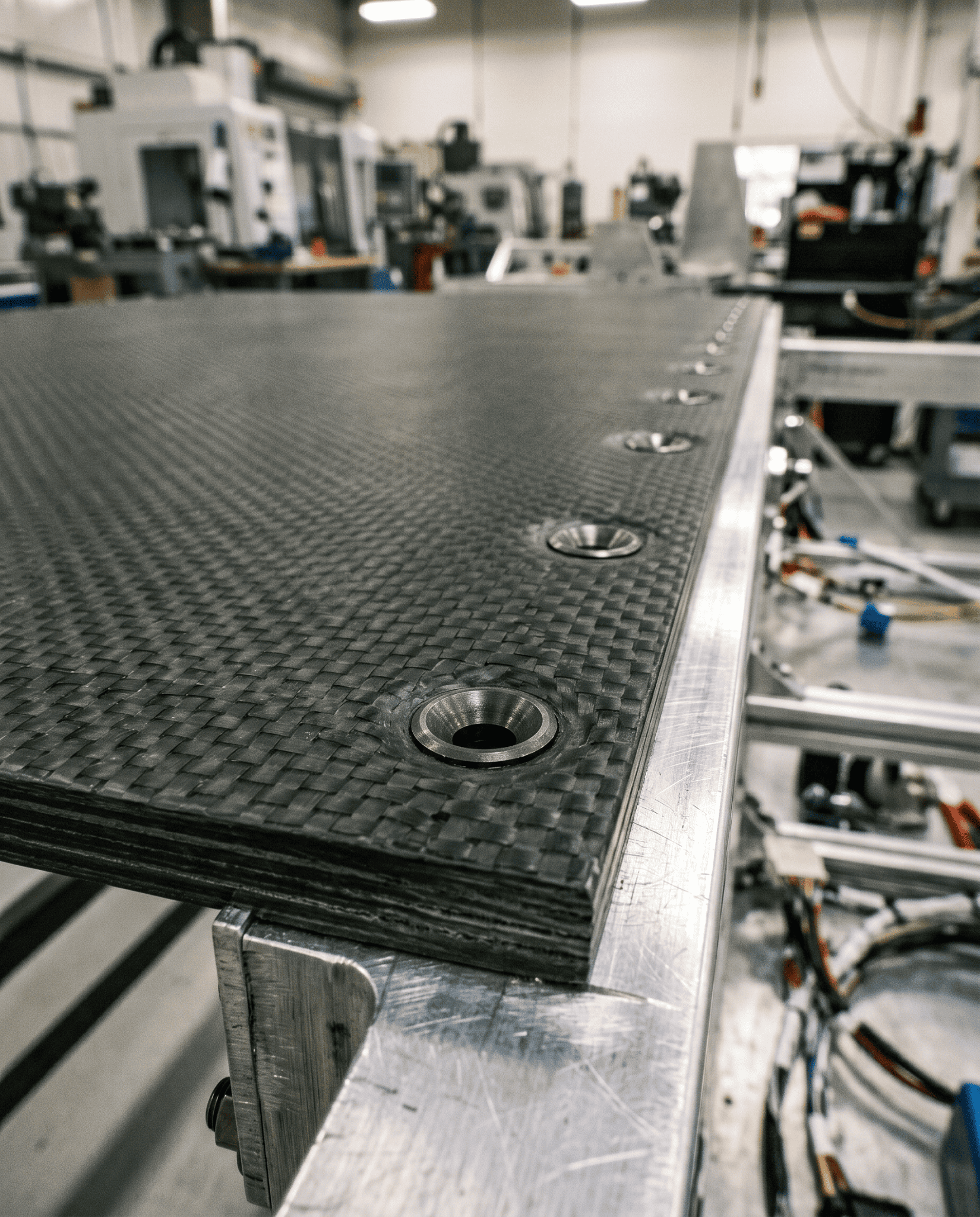
Countersunk fastener holes drilled through a CFRP laminate panel joined to an aluminium subframe — each hole a stress concentration at the highest-load point in the joint. AI-generated image.
Adhesive bonding eliminates holes but trades them for different problems: process sensitivity, inspection difficulty, temperature-limited service conditions, and the particular anxiety of an invisible bond line that cannot be easily assessed once it is cured.
The biological world, it turns out, solved this problem before CFRP existed. A September 2025 open-access study in the Journal of Composites Science (MDPI) formalizes the insight with experimental data, and the implications for how we think about composite joint design are worth reading carefully.
Three Beetles and a Design Principle
The study — by Khishigdorj Davaasambuu, Animesh Kumar Basak, Yu Dong, and Alokesh Pramanik of Curtin University and the University of Adelaide — opens with an observation about beetle elytra: the hardened wing covers that protect the insect's body. Specifically, about the suture lines where those covers meet.
Three species drive the analysis: Phloeodes diabolicus, Asbolus verrucosus, and Cryptoglossa muricata. Cross-sections of their elytra sutures reveal a two-part interlocking architecture that the engineering literature had not fully translated into manufactured joints. There is a primary interlock — a tooth-and-lobe geometry that resists the dominant pull-out load — and alongside it, a set of secondary ridges and overhanging features on either side of the main joint. These auxiliary structures do not primarily carry the tensile load. They prevent the female part of the joint from rotating outward.
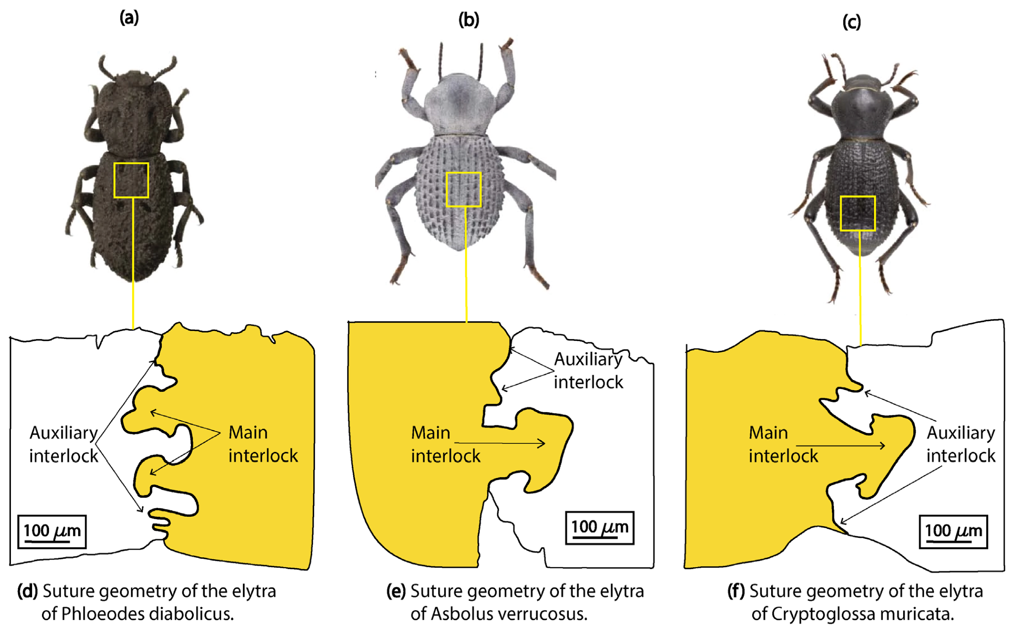
Three beetle species (Phloeodes diabolicus, Asbolus verrucosus, Cryptoglossa muricata) and cross-sections of their elytra sutures — showing the primary interlocking tooth geometry and the secondary auxiliary ridges that prevent the female part from bending outward. The auxiliary ridge is the biological feature this study translates into engineered joints. Figure 1 from: Davaasambuu, K.; Basak, A.K.; Dong, Y.; Pramanik, A. "Bio-Inspired Novel Joints with Superior Mechanical Performance." J. Compos. Sci. 2025, 9, 501. https://doi.org/10.3390/jcs9090501 — © 2025 by the authors. Licensed under CC BY 4.0.
That distinction is the paper's central contribution. The failure mechanism in conventional engineered interlocking joints — dovetail, T-slot, elliptical — is almost universally the same: outward bending of the female component's mortise groove, which progressively disengages the interlock from below the load. According to the paper, these secondary ridges physically restrain that rotation — preventing the bending from reaching the point of interface disengagement.
Davaasambuu et al. is not the first paper to draw inspiration from beetle armor for joint design — Rivera et al. (2020), cited throughout the paper, demonstrated that a beetle-derived elliptical joint matched riveted CFRP-aluminium performance — 19 MPa versus 18 MPa — without a single hole drilled. Xing et al. (2024) took a multi-species approach — drawing geometry from woodpecker anatomy, turtle shell architecture, and fossilized ammonite sutures — to identify which joint parameters push failure away from the interface and toward the material itself. Mirkhalaf et al. have demonstrated that elliptical interlocking geometries applied to glass can yield toughness gains of up to 200 times that of monolithic glass — and separately, double-circular variants applied to polymer substrates produced tenfold toughness improvements.
What the Davaasambuu et al. paper adds is the first systematic experimental translation of the auxiliary interlocking feature — not just the primary geometry — into manufactured joints, with a full benchmark against four existing bionic designs.
Six Joint Geometries Under Test
The experimental program evaluated six designs at identical dimensional parameters across all specimens — all specimens shared a common geometry: a 10 mm neck, a 22 mm-wide main interlock, 110 mm total engagement length, 30 mm specimen width, and 10 mm thickness throughout. An interlocking aspect ratio of 2.2 was held constant. Male parts were machined from nylon SUSTAMID 6G (bulk tensile strength: 86.5 MPa), female parts from aluminium 6061-T6 (300 MPa). All specimens were assembled at zero clearance and tested in uniaxial tension at 3 mm/min on a 50 kN Shimadzu universal testing machine, with DIC strain field analysis running in parallel via an iPhone 11 Pro at 60 FPS.
Four geometries represented the state of existing bionic joint research — each incorporating a primary interlock only:
Joint Types: Primary Interlock Only
Cross-sectional geometry, UTS, and bending onset for aluminium–nylon interlocked joints
Two novel designs incorporated auxiliary interlocking shoulders, directly translating the secondary ridge structures observed in beetle elytra sutures:
Primary + Auxiliary Interlocking
Dual-mechanism joints combining scarf/wavy geometry with hump interlocks — aluminium to nylon
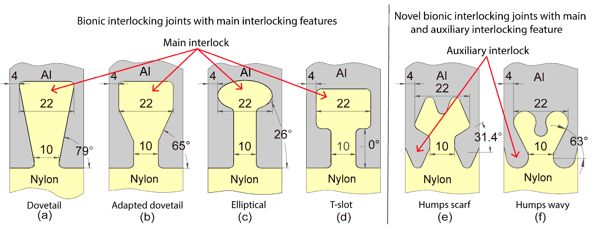
All six joint geometries drawn to scale: the four control designs (dovetail, adapted dovetail, elliptical, T-slot) carry only a primary interlock; the two novel designs (humps scarf, humps wavy) add auxiliary shoulder features on either side of the main interlocking tooth. The shoulder is the structural addition the paper tests. Figure 2 from: Davaasambuu, K.; Basak, A.K.; Dong, Y.; Pramanik, A. "Bio-Inspired Novel Joints with Superior Mechanical Performance." J. Compos. Sci. 2025, 9, 501. https://doi.org/10.3390/jcs9090501 — © 2025 by the authors. Licensed under CC BY 4.0.
The Results, and Why They Look the Way They Do
The tensile strength data across all six joints tells a clear story:
Ultimate Tensile Strength — All Six Joints
Aluminium–nylon interlocked joints, primary interlock only vs. primary + auxiliary designs
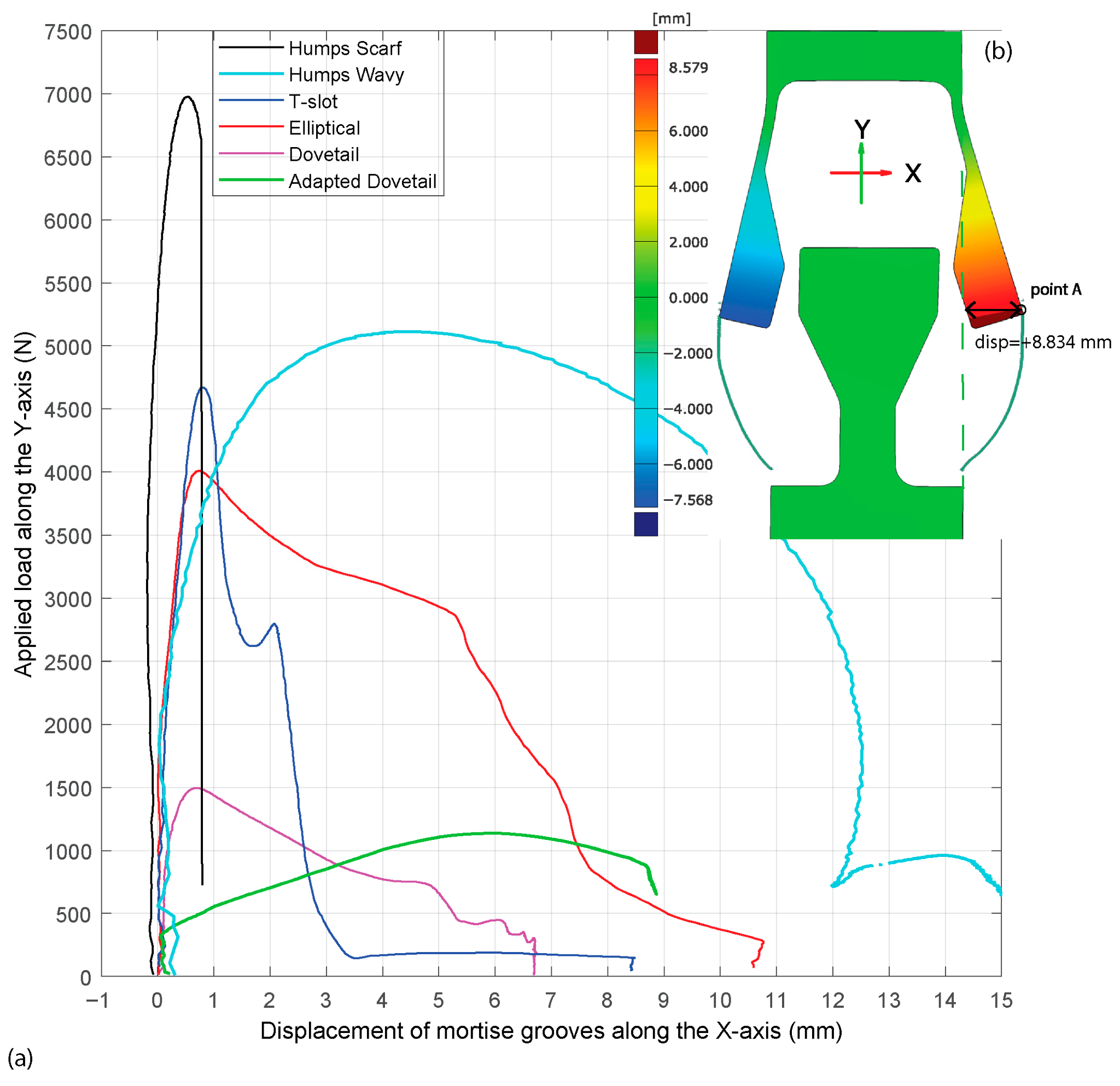
Load vs. lateral mortise groove displacement for all six joints: the adapted dovetail begins bending at ~400 N, the dovetail at ~1000 N, elliptical and T-slot hold to ~2500 N — and the humps scarf groove does not move until ~6000 N. Panel (b) shows the DIC reference point used to measure that displacement. The gap between these curves is the mechanical story the paper is telling. Figure 5 from: Davaasambuu, K.; Basak, A.K.; Dong, Y.; Pramanik, A. "Bio-Inspired Novel Joints with Superior Mechanical Performance." J. Compos. Sci. 2025, 9, 501. https://doi.org/10.3390/jcs9090501 — © 2025 by the authors. Licensed under CC BY 4.0.
The paper's explanation is built on DIC measurements of mortise groove displacement. In the dovetail, the aluminium female part began bending at approximately 1000 N — far below any material-limited threshold. The adapted dovetail started bending at 400 N. Once bending begins, the interlocking geometry that was carrying tensile load becomes a lever arm that amplifies the disengagement force: the geometry works against itself.
The humps scarf joint's mortise groove did not register appreciable displacement until approximately 6000 N. According to the paper, the trapezoidal auxiliary shoulders redirect the bending load back through the male part's neck region, short-circuiting the lever arm mechanism. With bending suppressed, load transfer concentrates in the nylon neck, and the joint eventually fractures there — inside the material, not at the interface.
That distinction matters: a joint that fails in the material has reached the geometric design's theoretical ceiling. A joint that fails at the interface is leaving load capacity unrealized.
For the T-slot and elliptical configurations, the mortise groove remained effectively rigid up to approximately 2500 N — a threshold more than twice what the dovetail designs could sustain — and this is what underpins their substantially higher strength relative to the dovetail variants.
The humps wavy joint tells a complementary story. Its curved auxiliary features are more compliant than the rectangular shoulders of the humps scarf, allowing progressive deformation that distributes strain across a wider interface region. The penalty is a lower peak strength (16.3 MPa vs 22.6 MPa), but the benefit is greater toughness — the ability to absorb energy before final failure — and the highest stiffness of any tested joint at 3304.5 N/mm.
Stiffness & Toughness — All Six Joints
Ordered lowest to highest — aluminium–nylon interlocked joints, control vs. novel designs
The practical implication: these are not simply better and worse versions of the same design. The humps scarf joint and the humps wavy joint occupy different positions in the strength-toughness design space, and the choice between them is a function of the structural requirement — maximum load capacity, or maximum energy absorption before failure.
Benchmarking Against Everything Else
A standout feature of the Davaasambuu et al. paper is its normalized comparison of aluminium-nylon joint performance across 18 configurations drawn from the literature, spanning friction stir welding, injection moulding, hot pressing, laser welding, additive manufacturing, and adhesive bonding. Because those studies use nylon grades with bulk strengths ranging from 81 MPa to 404 MPa (depending on fiber reinforcement content), raw MPa comparisons are misleading. The paper normalizes each joint's measured strength by its own nylon material's bulk tensile strength.
Normalised Joint Strength
Selected configurations — this study vs. external literature techniques
The injection moulding result at the top of the chart (Wang et al., 2023) uses chemically functionalized aluminium with reactive epoxide silane coupling to create what is effectively a hybrid mechanical-chemical bond — a fundamentally different mechanism from purely geometric interlocking. Setting that aside, the humps scarf joint leads all mechanical interlocking configurations, and both novel designs outperform friction stir welded, adhesive bonded, and additively manufactured joint configurations on a normalised basis. The paper's authors read these results as support for rethinking how dissimilar-material joints are made — geometric interlocking without chemical treatment or welding heat can reach normalised strength levels that process-intensive methods spend significant manufacturing cost to achieve.
Addcomposites' Perspective: From Machined Specimens to AFP Tow Paths
The analysis below reflects Addcomposites' own interpretation of the research implications for AFP-manufactured CFRP structures. The paper's authors make no claims about AFP manufacturing, and this section should not be read as representing their views or conclusions.
The Davaasambuu et al. study was conducted on machined aluminium-nylon specimens. The nylon male parts were produced by CNC machining, not fiber placement. The conclusions — that auxiliary interlocking features suppress mortise groove bending, shift failure into the material, and can double joint toughness relative to conventional designs — are geometric and mechanical, and they transfer to any material system where the interlocking geometry can be realized at the required dimensional tolerance.
For AFP-manufactured CFRP panels and frames joined to metallic substructures, the path is direct. The aluminium female part is CNC-machined — exactly as in the experimental program. The CFRP male part, today typically drilled for fasteners, can instead be AFP-layered with tow paths that build the interlocking hump geometry into the panel edge or beam end during part fabrication. Fiber orientation in the neck region carries the primary tensile load; ply management at the shoulder feeds load into the auxiliary interlocking feature rather than into a hole.
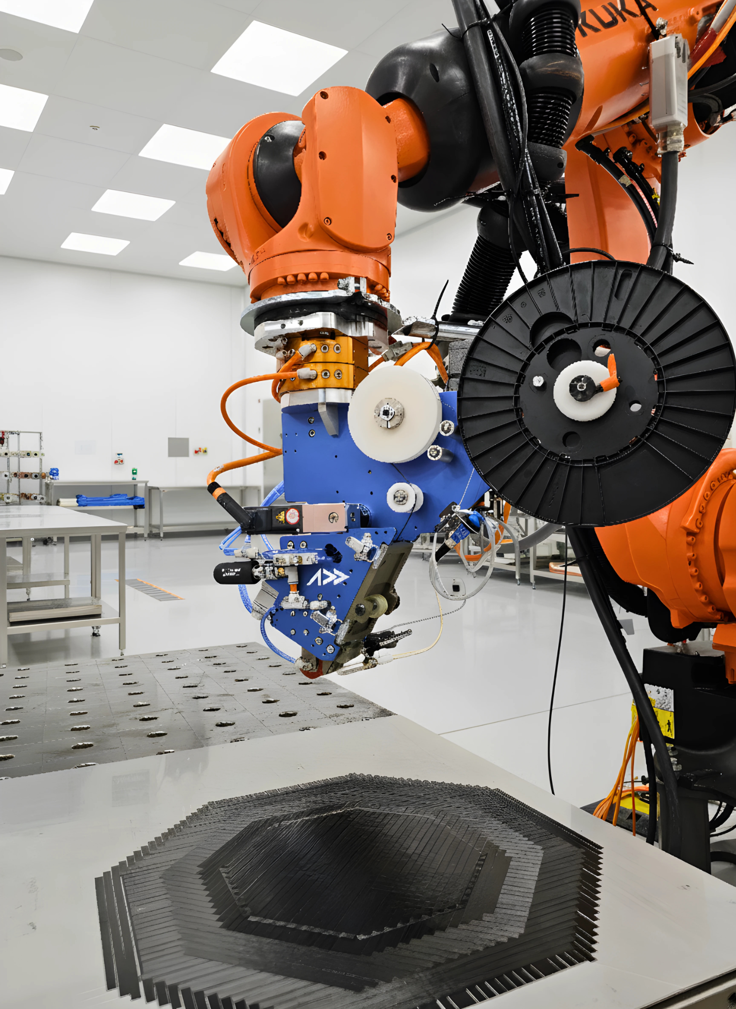
The AFP-XS head depositing carbon fiber tow onto a profiled CFRP preform — tow path orientation and layup sequence are programmable parameters, making edge geometry a design variable rather than a post-machining step.
This matters most at two specific failure modes the paper identifies. First, the neck fracture failure mode that the humps scarf joint achieves is essentially an in-plane tensile fiber failure — the mode that continuous-fiber AFP layups are most efficient at resisting. AFP tow path orientation in the neck can be aligned with the load direction with a precision unachievable by hand layup or by post-machining. Second, the paper's conclusions flag neck width as the primary geometric lever for further improvement — a wider neck expands the load-bearing cross-section and reduces the stress concentration that caused fracture in the humps scarf design. In AFP, neck width is a tow path parameter, not a tooling change.
The paper also notes that both novel designs enable interference-fit assembly without generating the local stress at mortise grooves that conventional interlocking joints produce under press-fit conditions. This is significant for AFP-manufactured parts: it means the CFRP male component can be assembled into the aluminium female without inducing delamination-promoting compressive stress at the joint interface during assembly.
The dimensional tolerance requirements are real — all specimens in the paper were assembled at zero clearance, and all were machined by CNC and EDM to achieve that fit. AFP-XS part-to-part repeatability, combined with a machined aluminium female part, provides the dimensional consistency this design principle requires. That same repeatability is what makes iterating on neck width, hump geometry, or auxiliary feature angle a practical design exploration rather than a one-off fabrication exercise.
Three Takeaways for Joint Design
The research published by Davaasambuu et al. supports three conclusions that are directly applicable to structural composite joint design, independent of the AFP context:
Interlocking angle is not the primary design variable
The paper demonstrates that a 65° adapted dovetail performs worse than a 79° standard dovetail — reversing the expected trend. Bending resistance of the female mortise groove matters at least as much as the angle, and for some configurations, more. Optimizing angle without addressing bending produces unpredictable results.
Auxiliary features are load path engineering, not decoration
The performance gap between the novel joints and the conventional bionic joints — 1.7× to 6× depending on the comparison — is attributable entirely to one structural feature that required no increase in joint complexity: a shoulder that prevents the female part from rotating. In load path terms, it eliminates the dominant failure mechanism rather than working around it.
The design target is material failure, not interface failure
Any joint that fails at the aluminium-polymer interface is failing because of geometry, not because of the materials. The humps scarf joint's failure mode — fracture through the nylon neck — means the geometry was successful. Future optimization of that joint is a material optimization problem, which is a solved problem in engineering. Future optimization of a joint that fails at the interface is a geometry problem that has not been solved.
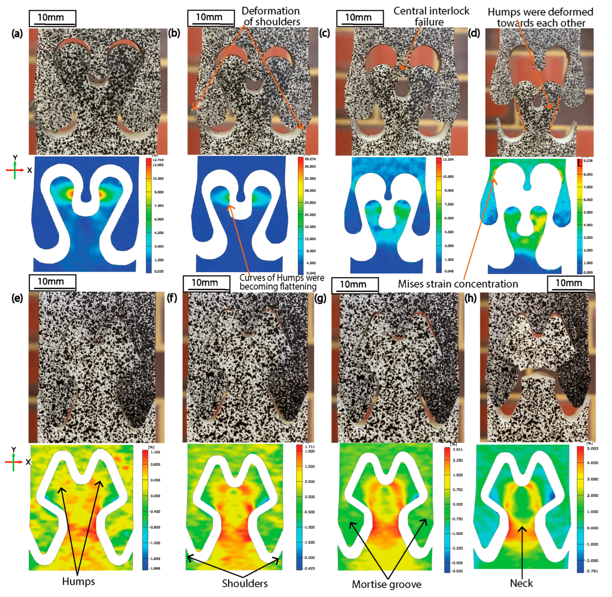
DIC axial strain sequence for the humps scarf joint: (e) uniform strain at initial load, (f–g) strain concentrating progressively in the nylon neck while the aluminium mortise grooves remain unbent, (h) final fracture through the nylon neck — the aluminium part intact. Failure inside the material, not at the interface. Figure 6 (panels e–h) from: Davaasambuu, K.; Basak, A.K.; Dong, Y.; Pramanik, A. "Bio-Inspired Novel Joints with Superior Mechanical Performance." J. Compos. Sci. 2025, 9, 501. https://doi.org/10.3390/jcs9090501 — © 2025 by the authors. Licensed under CC BY 4.0.
Read the Research
All experimental data, figures, and joint geometry descriptions referenced in this post are drawn from:
Davaasambuu, K.; Basak, A.K.; Dong, Y.; Pramanik, A. "Bio-Inspired Novel Joints with Superior Mechanical Performance." Journal of Composites Science 2025, 9, 501. Full text and DOI: https://doi.org/10.3390/jcs9090501 Open Access — © 2025 by the authors. Licensed under CC BY 4.0.
If you're designing CFRP-to-metal connections and want to discuss how AFP tow path programming can translate interlocking geometry into manufactured parts, contact the Addcomposites team.
Learn More
Get in touch to discuss your CFRP-to-metal connection and AFP tow path programming application →
Contact Us for a ConsultationReferences
- Davaasambuu, K.; Basak, A.K.; Dong, Y.; Pramanik, A. "Bio-Inspired Novel Joints with Superior Mechanical Performance." Journal of Composites Science 2025, 9, 501. https://doi.org/10.3390/jcs9090501
- Rivera, J. et al. "Toughening mechanisms of the elytra of the diabolical ironclad beetle." Nature 2020, 586, 543–548. https://doi.org/10.1038/s41586-020-2813-8
- Xing, Y. et al. "Mechanics of elliptical interlocking sutures in biological interfaces." Acta Biomaterialia 2024, 192, 90–100.
- Mirkhalaf, M.; Dastjerdi, A.K.; Barthelat, F. "Overcoming the brittleness of glass through bio-inspiration and micro-architecture." Nature Communications 2014, 5, 3166.
- Wang, B. et al. "Functionalization of aluminum alloy surface with reactive epoxide silane to induce ultra-high strength polyamide 6/aluminum alloy composite joint." Applied Surface Science 2023, 626, 157231.
