CFRP Battery Enclosures for −40 °C Side-Pole Impact: How Bayesian AI Surrogates Cut the Design Loop From Weeks to Hours
A new open-access study trains machine-learning surrogates on just 50 crash simulations to map an entire lightweight CFRP enclosure design space against China's incoming GB 38031-2025 safety regime — and shows why "probably safe" beats "passes on paper" for cold-weather composites.
When an electric vehicle is built to survive a cold-climate market, the battery enclosure has a harder job than the spec sheet suggests. Carbon fiber reinforced polymer (CFRP) is the obvious lightweighting candidate — high specific stiffness, high specific strength — but the same material behaves differently at −40 °C than it does in a comfortable lab. And the regulatory bar it has to clear is moving.
A study published 13 February 2026 in Batteries (MDPI), open access under CC BY 4.0, tackles exactly this intersection. Desheng Zhang, Jieguo Liao, Longbin Wang, Zhenxin Sun, and Han Zhang set out to jointly minimize two things for a CFRP-enabled battery pack enclosure — total mass and peak intrusion — under an extreme-cold side-pole extrusion scenario aligned to China's GB 38031-2025 standard. The twist is how they do it: instead of grinding through hundreds of expensive finite element (FE) crash runs, they train Bayesian surrogate models on a deliberately tiny dataset and let probability, not a single deterministic number, decide what counts as safe.
This post walks through what the paper actually demonstrates, visualizes its real numbers, and — kept clearly separate — offers our own read on what it means for teams manufacturing CFRP enclosures with automated fiber placement.
A note on framing
Throughout, "the paper shows" or "according to the authors" marks findings from the study itself. "Our perspective" marks Addcomposites' own commentary. The study's authors did not review, endorse, or contribute to this post, and nothing here should be read as their validation of Addcomposites or its products.
The regulatory clock that makes this urgent
China's revised mandatory national standard GB 38031-2025 ("Safety Requirements for Power Batteries Used in Electric Vehicles") was released in 2025 and applies to all newly type-approved EV models in China from 1 July 2026, with existing type-approved models required to comply from 1 July 2027. It is widely described as the strictest battery-safety standard yet, comprising 7 single-cell tests and 17 battery pack or system tests, including a newly added battery bottom-impact test and a post-fast-charge safety test. Its headline change is the elevation of a mandatory "no fire, no explosion" criterion: batteries must not catch fire or explode during or after an internal thermal runaway event.
Mechanical abuse is one of the paths to that thermal runaway. The paper's contribution sits on the structural side of the problem: it adopts the standard's lateral rigid-pole extrusion protocol and studies it at a deliberately punishing −40 °C, because cold changes how composite enclosures absorb and resist intrusion. The −40 °C condition is the authors' chosen extreme-cold design scenario layered onto the standard's mechanical test — not a separate temperature mandated by the regulation.
Our perspective
For any supplier with an EV program touching the Chinese market, July 2026 is no longer abstract. Structure-level verification of the enclosure is now a gate, not a nice-to-have — and that raises the value of any methodology that can qualify a CFRP design without an open-ended simulation budget.
The cold-weather composite data trap
Here is the engineering knot the paper describes. CFRP at low temperature is, in the authors' framing, "available but not self-consistent." Plenty of low-temperature coupon data exists, but the results shift with which fibre–resin pairing is used, how the plies are stacked, how the laminate was cured, and even how the test itself is defined. Stitching parameters together from multiple sources risks importing hidden inconsistencies that quietly corrupt a simulation. Building a fully consistent −40 °C database for every candidate layup, on the other hand, is cost-prohibitive.
The paper's response is a single-anchor strategy: pick one coupon-level dataset with measured −40 °C properties, use it consistently across every run, record the provenance of each parameter — and then, rather than pretend the inputs are certain, treat that scatter as a first-class part of the design problem instead of a footnote.
The second bottleneck is compute. Explicit-dynamics pole-crash simulations are slow because the solver's safe step size is dictated by the tiniest element and how fast a wave crosses it, so the dense meshing around the contact zone drags runtimes up. Multiply that by nine design variables and brute-force FE simply cannot afford to explore the space.
- Fiber / resin variation
- Layup differences
- Cure route variation
- Test metric used
- Tiny stable time step (explicit FE crash run)
- Fine contact meshing required
- 9 design variables
- Repeat per scenario
The workflow at a glance
The study spends a fixed budget of exactly 50 high-fidelity FE runs and never exceeds it. Those 50 runs are partitioned deterministically — using a fixed seed so the split is reproducible — into a 37 / 5 / 5 / 3 structure: 37 runs to train the first surrogate, two enrichment batches of 5 runs each that grow the training set to 42 and then 47, and a strict 3-run hold-out that is quarantined from all fitting, tuning, and selection.
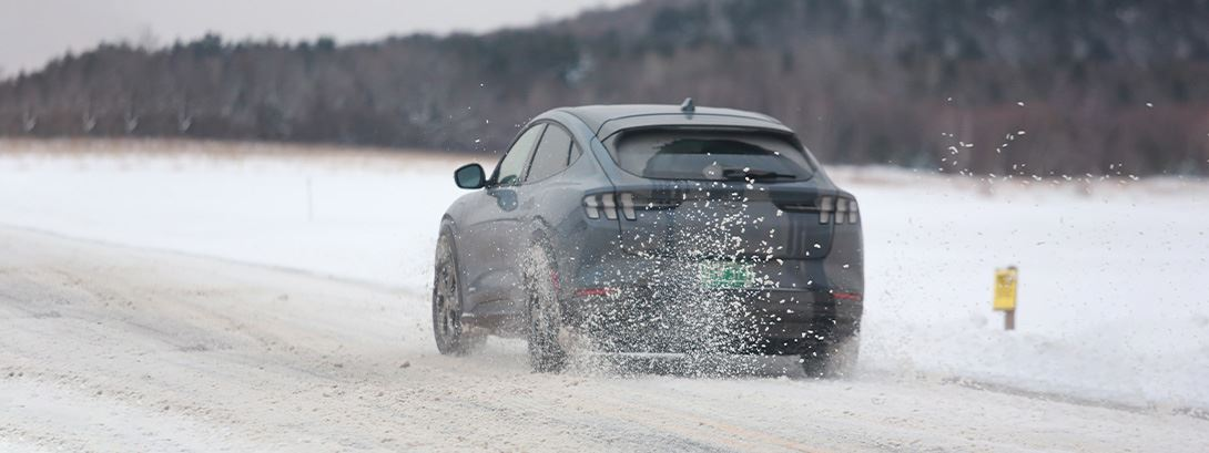
Six-stage workflow overview: −40 °C side-pole impact scenario (battery enclosure with rigid pole) → high-fidelity FE DOE (wireframe mesh model) → Bayesian surrogate modeling with uncertainty band (GPR/BART) → PoF screening against threshold η → bimodal Pareto front (two separate dot clusters) → selected design with FE rerun confirmation (shield + checkmark). Graphical abstract from: Desheng Zhang, Jieguo Liao, Longbin Wang, Zhenxin Sun, Han Zhang. "Uncertainty-Aware Lightweight Design of CFRP Battery Enclosure Under Extreme Cold Side-Pole Impact via Bayesian Surrogates." Batteries 2026, 12, 61. https://doi.org/10.3390/batteries12020061 — © 2026 by the authors. Licensed under CC BY 4.0 (https://creativecommons.org/licenses/by/4.0/).
Six-stage surrogate workflow
Diagram built by Addcomposites from the 37/5/5/3 protocol described in Zhang et al., Batteries 2026, 12, 61 ( https://doi.org/10.3390/batteries12020061) .
Three scalar responses come out of every FE run: enclosure mass M, peak intrusion L along the loading direction, and peak von Mises stress in the lateral anti-collision beam (Stress). Mass and intrusion are the two objectives to minimize; stress is treated as a feasibility constraint rather than an objective.
The design vector has nine variables: five are component thicknesses (end bulkhead, cooling plate, load-distribution support plate, lower case, and lateral anti-collision beam), and four are CFRP layup weights for the 0°, +45°, −45°, and 90° ply orientations. Those four weights are normalized into ply ratios that sum to one and then mapped to integer ply counts with a rounding-and-repair step that, among other things, keeps the ±45° plies balanced.
(+5 → 42)
(+5 → 47)
reserved
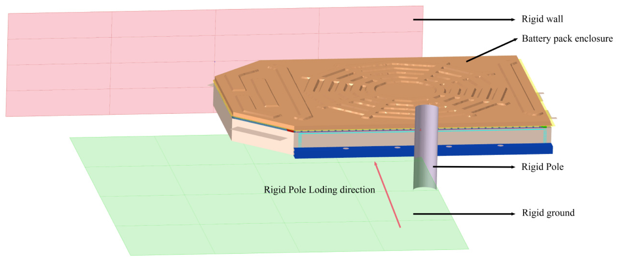
Figure 1 from: Desheng Zhang, Jieguo Liao, Longbin Wang, Zhenxin Sun, Han Zhang. "Uncertainty-Aware Lightweight Design of CFRP Battery Enclosure Under Extreme Cold Side-Pole Impact via Bayesian Surrogates." Batteries 2026, 12, 61. https://doi.org/10.3390/batteries12020061 — © 2026 by the authors. Licensed under CC BY 4.0 (https://creativecommons.org/licenses/by/4.0/).
FE setup
The paper's Figure 1 shows the assembly-level model: a 150 mm-diameter rigid pole is pushed along −Z into the long side of the enclosure under controlled displacement, with the enclosure held between two rigid walls;
the run halts at whichever limit comes first — 100 kN of reaction force, or intrusion equal to 30 % of the loaded dimension. An application-level protection rule is added on top of the standard pass/fail criteria — intrusion must stay below the 20 mm packaging clearance between the enclosure and the modules.
Teaching a model on only 50 crash runs
The primary surrogate is BART (Bayesian Additive Regression Trees), chosen because it copes with sharply nonlinear behaviour and interacting variables even on a thin dataset, and — critically — it hands back a spread of possible values rather than one lone number. A separate BART model is fit for each of M, L, and Stress. As a guard against leaning on one model family, the authors also fit a Gaussian process regression (GPR / Kriging) surrogate with a Matérn kernel as an independent cross-check on the same data split.
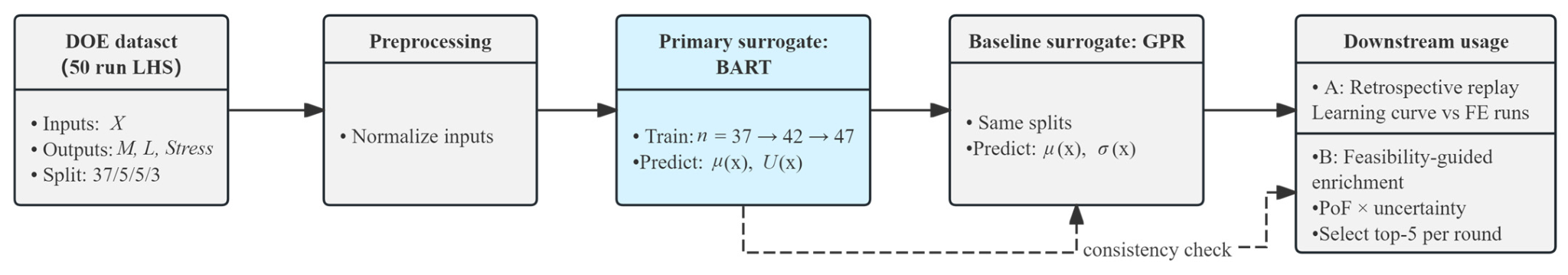
Flowchart of the full surrogate workflow: 50-run DOE split (37/5/5/3) → input normalisation → BART primary surrogate trained sequentially at n = 37, 42, 47 → GPR reference model on the same splits (dashed consistency-check arrow) → downstream outputs: retrospective replay and feasibility-guided enrichment (PoF × uncertainty, top-5 per round). Figure 5 from: Desheng Zhang, Jieguo Liao, Longbin Wang, Zhenxin Sun, Han Zhang. "Uncertainty-Aware Lightweight Design of CFRP Battery Enclosure Under Extreme Cold Side-Pole Impact via Bayesian Surrogates." Batteries 2026, 12, 61. https://doi.org/10.3390/batteries12020061 — © 2026 by the authors. Licensed under CC BY 4.0 (https://creativecommons.org/licenses/by/4.0/).
To track how accuracy evolves as data is added, the paper uses a prequential (test-then-update) replay and reports normalized RMSE at each stage. The pattern is the interesting part. According to the authors, intrusion L becomes easier to predict as runs accumulate, mass M stays low-error throughout, and stress stays hard to pin down, which they tie to how sharply it concentrates at the contact point.
The paper notes that the GPR cross-check follows the same trends — L learns reliably, Stress stays difficult — which is the point of running it. That divergence in difficulty between L and Stress is what drives the entire feasibility strategy.
42 runs → 0.545
47 runs → 0.523
42 runs → 0.091
47 runs → 0.180
42 runs → 0.170
47 runs → 0.071
Why stress gets a probability, not a hard line
The reasoning the paper builds on: if your stress predictor is the least reliable model you have, enforcing it as a crisp pass/fail line on a single predicted number is asking for trouble. A design that looks fine under the mean prediction might tip over the limit once you actually re-run the high-fidelity simulation.
The paper's answer is a probability-of-feasibility (PoF) gate. Instead of checking whether the single predicted stress is below the cap, it asks: across the surrogate's full posterior of predicted stresses, what fraction fall below the cap? That fraction is the PoF, tallied directly from the BART posterior draws by Monte Carlo counting — with no bell-curve assumption layered on top.
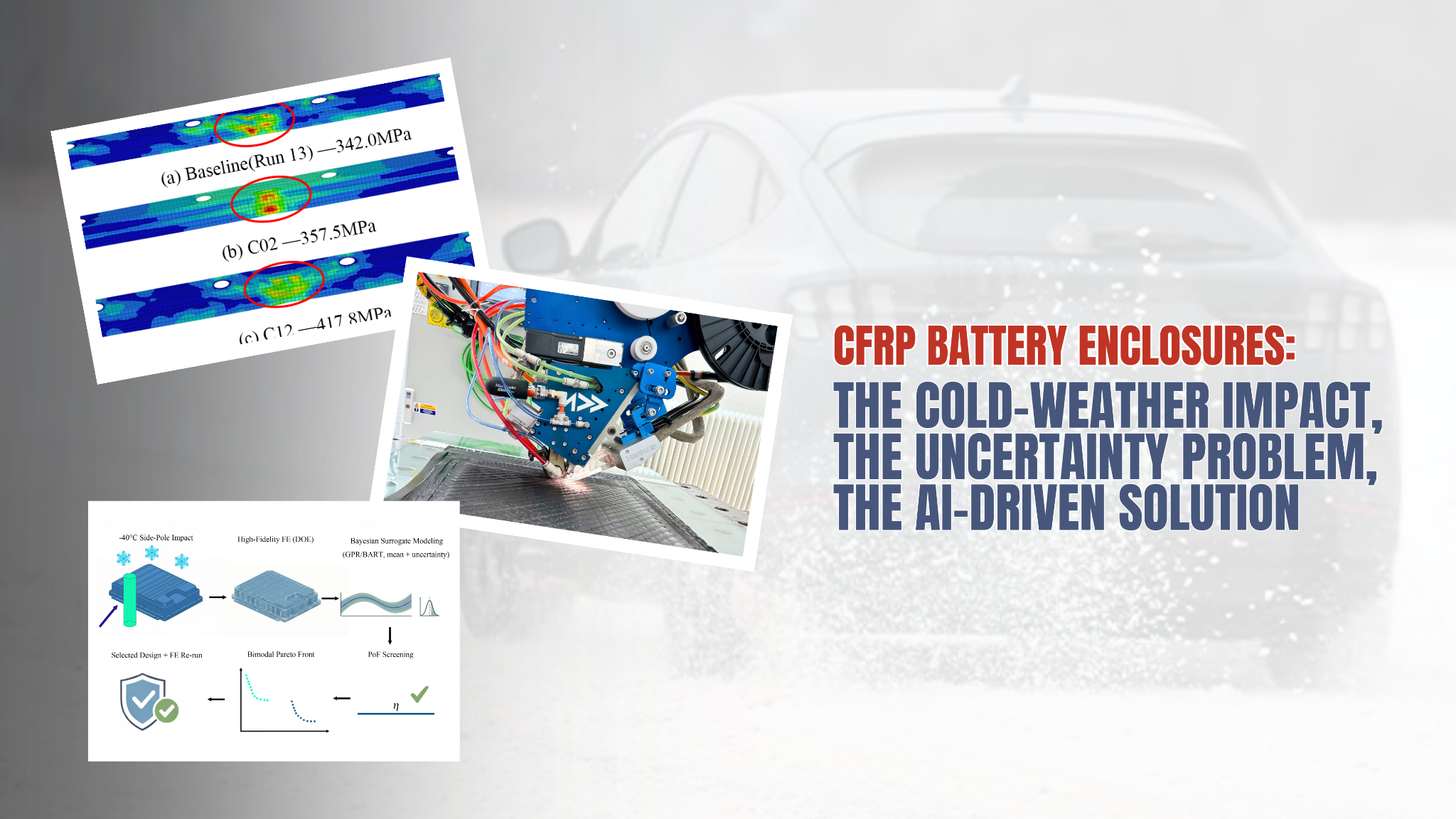
A design is admitted to the feasible set only if its PoF is at least η = 0.90. The stress cap itself is anchored to the baseline design: σ_lim = 1.20 × σ_base, where σ_base = 342.0 MPa is the baseline's peak stress under the same −40 °C setup, giving σ_lim = 410.4 MPa with a deliberate 20 % screening margin.
Ground-truth simulation confirms the shortlisted design.
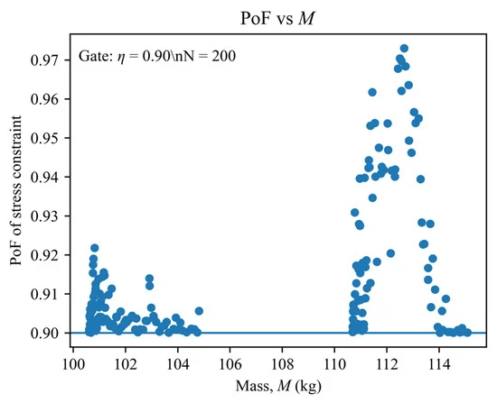
Scatter plot (n = 200 candidate designs) with PoF of the stress constraint on the y-axis (0.90–0.97) and enclosure mass M on the x-axis (100–114 kg); a horizontal line marks the η = 0.90 screening gate. Dots cluster densely just above the threshold at lower masses (100–106 kg) and shift to higher PoF values at heavier masses (110–114 kg), showing where feasibility confidence is tight versus comfortable. Figure A1 from: Desheng Zhang, Jieguo Liao, Longbin Wang, Zhenxin Sun, Han Zhang. "Uncertainty-Aware Lightweight Design of CFRP Battery Enclosure Under Extreme Cold Side-Pole Impact via Bayesian Surrogates." Batteries 2026, 12, 61. https://doi.org/10.3390/batteries12020061 — © 2026 by the authors. Licensed under CC BY 4.0 (https://creativecommons.org/licenses/by/4.0/).
Pragmatic balance of the gate
The authors are explicit that 0.90 is a pragmatic balance — tight enough to block risky candidates, loose enough that good lightweight options aren't discarded while the stress model is still shaky. They recommend a stricter η = 0.95 for stress-critical sign-off, and they stress that PoF is for screening only; final acceptance is a deterministic check against σ_lim from a fresh FE run.
Feasible candidates are found by running NSGA-II (a standard multi-objective evolutionary optimizer; population 200, 400 generations, fixed seed) over the surrogate landscape, with the discrete thickness levels and the layup-to-ply mapping repaired on every offspring before evaluation.
Two designs, not one: the bimodal Pareto
One of the more visually striking results is that the feasible non-dominated set does not form a single smooth trade-off curve. It splits into two separate branches, and the paper traces the split to a single variable: the lower-case thickness, x₄, which turns out to be bimodal in the data and effectively acts as a regime selector.
The authors explain the two regimes mechanically. Branch I — thinner lower case, lighter — is more compliant in out-of-plane bending, so it spreads the pole load over a broader path and reduces intrusion mainly by raising overall structural stiffness (a "global compliance" response). Branch II — thicker lower case, heavier — stiffens the region near the pole contact, holds off local crumpling and cross-section flattening, and funnels load into the neighbouring rails and cross-members, buying slightly lower intrusion at the cost of more mass and greater sensitivity to contact-driven stress peaks. Notably, the paper observes that feasible designs grow scarce at the lightest extreme, which it reads as stress compliance becoming the binding factor there.
The paper's Figure 7 plots this feasibility-aware Pareto set at −40 °C, distinguishing feasible non-dominated points from infeasible ones under the PoF ≥ 0.90 gate.
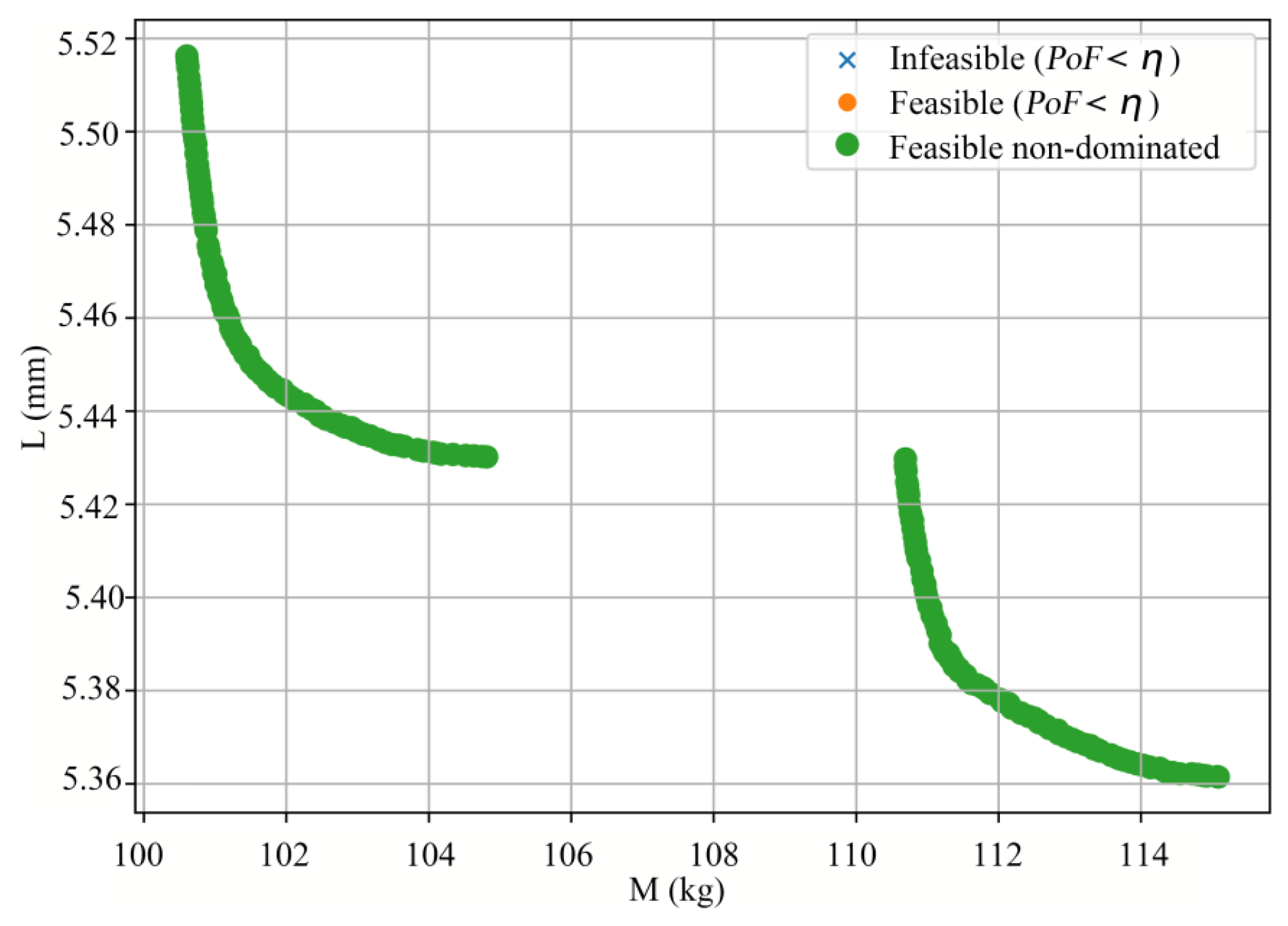
Figure 7 from: Desheng Zhang, Jieguo Liao, Longbin Wang, Zhenxin Sun, Han Zhang. "Uncertainty-Aware Lightweight Design of CFRP Battery Enclosure Under Extreme Cold Side-Pole Impact via Bayesian Surrogates." Batteries 2026, 12, 61. https://doi.org/10.3390/batteries12020061 — © 2026 by the authors. Licensed under CC BY 4.0 (https://creativecommons.org/licenses/by/4.0/).
To pick a representative design without hand-waving, the paper reduces each branch to six candidates by interval filtering (12 total), then ranks them with TOPSIS using mass and intrusion as equally weighted cost criteria. Re-running the ranking with a GPR-based variant gives a Kendall's τ of 0.606 — moderate agreement — and design C02 from Branch I emerges as the representative pick.
The reality check: independent FE reruns
This is where the probabilistic framing earns its keep. The authors take three surrogate-selected candidates back to full FE simulation: C02 (the Branch I TOPSIS pick), C12 (a Branch II design sitting right at the PoF ≈ 0.90 boundary), and C09 (a higher-margin Branch II design at PoF ≈ 0.95). Acceptance is judged deterministically against σ_lim = 410.4 MPa.
Any candidate whose FE-verified stress exceeds this threshold is rejected — regardless of PoF score
The C12 result is the cautionary tale the paper leans on. A candidate that satisfied the 0.90 screen nonetheless exceeded the stress cap once independently re-simulated (417.8 MPa against the 410.4 MPa limit). The authors' reading is that designs sitting right at the gate keep a genuine chance of failing, precisely because the governing stress is so concentrated at the contact; that a point-estimate model discarding the spread would have waved C12 through; and that stress-critical components therefore warrant the stricter η = 0.95 gate — which would have favored a higher-margin design like C09.
The reruns also surfaced a systematic quirk: intrusion L was consistently underpredicted by the surrogate (by roughly 9–13 % on these candidates), making the surrogate's intrusion estimates slightly optimistic in this local region, even as the relative ordering between designs held up. Mass tracked the FE results within about ±6 %.
The paper's Figure 10 shows the −40 °C stress contours on the lateral anti-collision beam for the baseline, C02, and C12, with the stress concentration confined to the pole-contact zone.
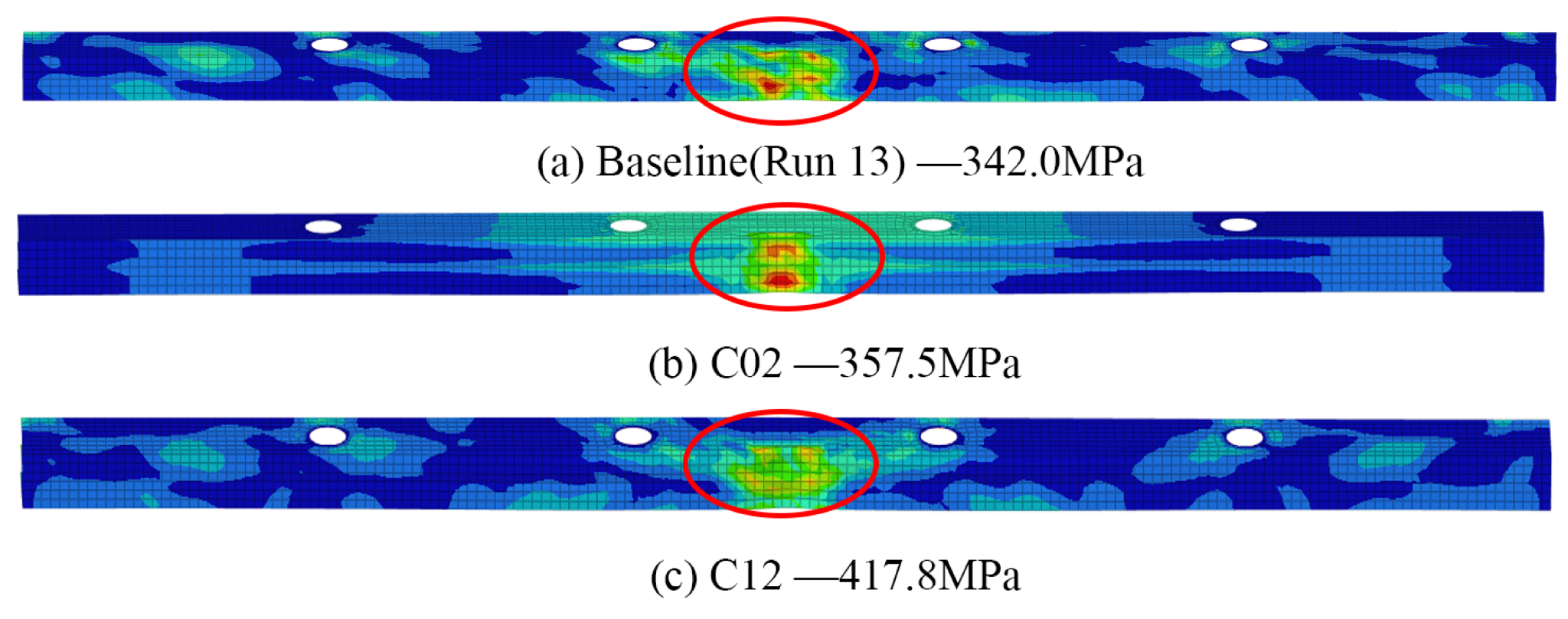
Figure 10 from: Desheng Zhang, Jieguo Liao, Longbin Wang, Zhenxin Sun, Han Zhang. "Uncertainty-Aware Lightweight Design of CFRP Battery Enclosure Under Extreme Cold Side-Pole Impact via Bayesian Surrogates." Batteries 2026, 12, 61. https://doi.org/10.3390/batteries12020061 — © 2026 by the authors. Licensed under CC BY 4.0 (https://creativecommons.org/licenses/by/4.0/). Described, not reproduced.
Hours, not weeks
The economic argument is blunt. The paper reports that one high-fidelity FE evaluation of this −40 °C side-pole case takes about 23 minutes on the workstation used, while a trained surrogate evaluation is sub-second — a median of 0.394 s per design, or 0.160 s when amortized over batch scoring.
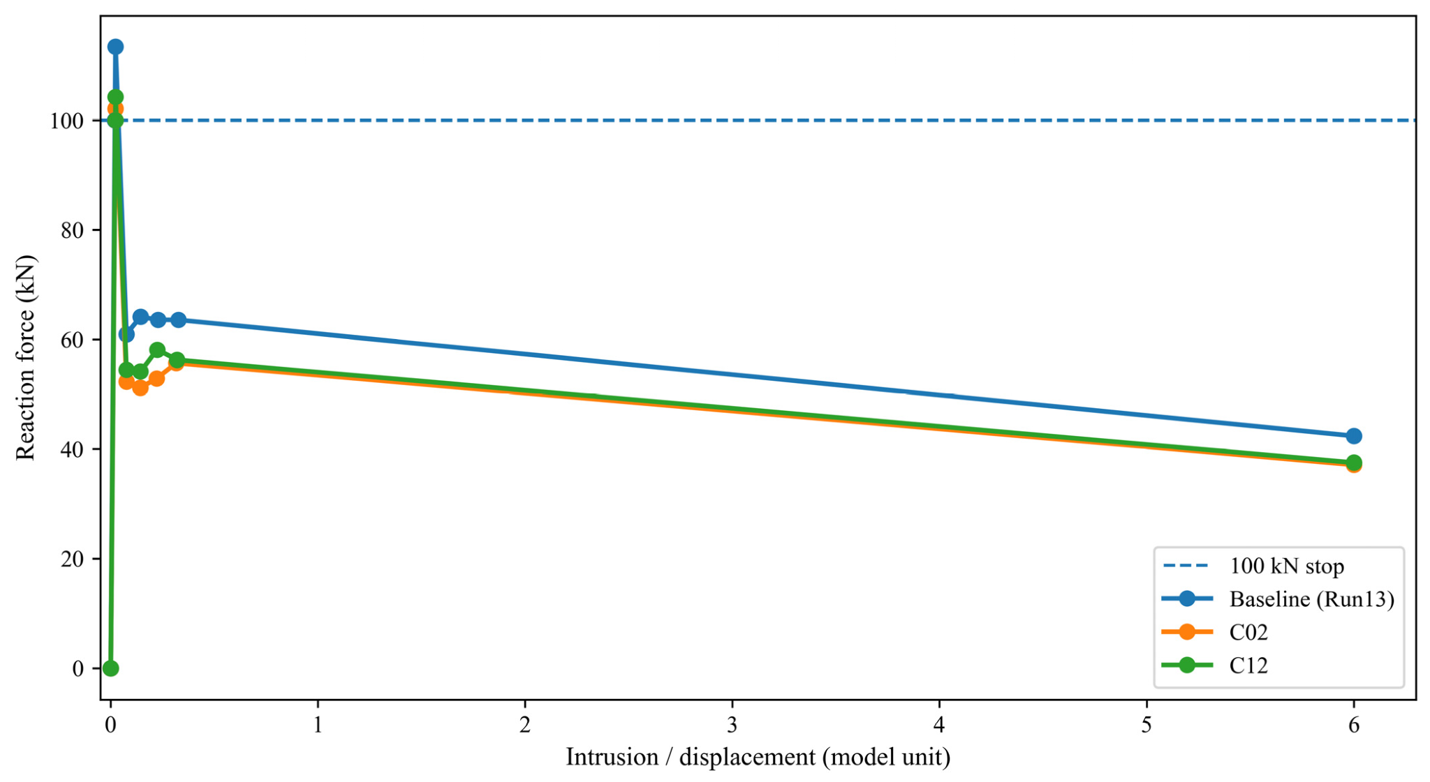
Reaction force (kN, y-axis, 0–100) versus intrusion/displacement (model units, x-axis, 0–6) for three −40 °C FE runs — baseline Run 13, C02, and C12 — plus a horizontal dashed line marking the 100 kN termination threshold; all three curves rise from near zero and intercept the stop line at different intrusion values, showing that each run terminates as soon as the reaction force criterion is met rather than running to a fixed displacement. Figure 11 from: Desheng Zhang, Jieguo Liao, Longbin Wang, Zhenxin Sun, Han Zhang. "Uncertainty-Aware Lightweight Design of CFRP Battery Enclosure Under Extreme Cold Side-Pole Impact via Bayesian Surrogates." Batteries 2026, 12, 61. https://doi.org/10.3390/batteries12020061 — © 2026 by the authors. Licensed under CC BY 4.0 (https://creativecommons.org/licenses/by/4.0/).
The portable asset is the workflow
The crucial caveat, which the paper makes itself: the surrogate does not replace FE. It replaces the exploration — letting an optimizer roam over thousands of candidate laminates cheaply — while the final, safety-relevant decision still comes from a small number of independent high-fidelity reruns.
The authors frame the portable asset as the workflow, not the model: you can reuse the recipe at another temperature, but you cannot reuse a model that only ever saw −40 °C data.
Where automated fiber placement fits in
The following is Addcomposites' own analysis, not a claim from the paper.
What stands out to us is that the paper's design knobs are precisely the things a manufacturing process has to be able to deliver. Two of the variables that move the answer most are CFRP component thicknesses — the lower case and the lateral anti-collision beam — and four more are layup orientation weights that get mapped to discrete 0° / +45° / −45° / 90° ply counts with balanced ±45° plies enforced. An optimizer can propose any laminate it likes; the question is whether the shop floor can build that laminate repeatably.
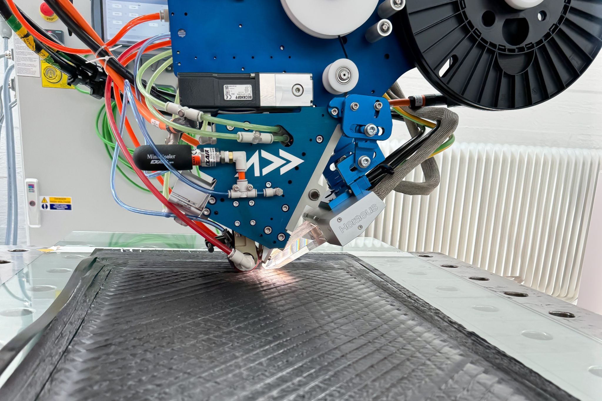
AFP-XS automated fiber placement head depositing CFRP tape, with multiple ply orientations visible on the laminate surface. © Addcomposites.
Closing the manufacturing gap
That is the gap automated fiber placement is built to close. The AFP-XS system lays carbon fiber tape with controlled, programmable ply orientation and thickness build-up, and AddPath lets you define and verify the stacking sequence digitally before a single ply is placed. The kind of orientation-grouped, ply-count-specific laminate the study optimizes over is exactly the class of design AFP is suited to produce — and to produce consistently enough that an FE-qualified configuration and the as-built part are the same part.
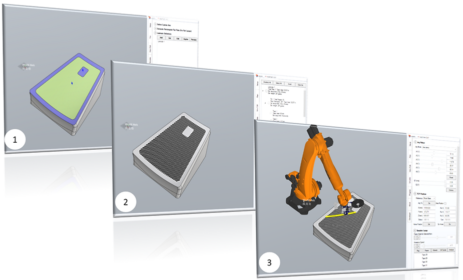
AddPath workflow: part geometry definition (1), automated tow-path planning across the laminate surface (2), and full robot motion simulation for pre-build verification (3). © Addcomposites.
Process repeatability and material model credibility
There is a second, subtler connection. The paper's whole premise is that −40 °C material data is scattered and process-dependent. Process repeatability is therefore not just a manufacturing virtue; it is what makes a single-anchor material model defensible — the more controlled the layup process, the more credible the assumption that one consistent property set describes every build.
Our perspective: For teams staring down GB 38031-2025 with a CFRP enclosure on the roadmap, the lesson we take from this study is that the design methodology and the manufacturing methodology have to be co-designed. A probabilistic, FE-frugal optimization loop tells you which laminate to build; a controllable AFP process is what lets you actually build the laminate the loop recommends — and lets you trust that the part you verify is the part you ship. Again, the study's authors make no claim about AFP, Addcomposites, or any commercial system; this connection is ours.
What the paper is careful not to claim
Good research states its own limits, and this one does. A few worth flagging, in the authors' own framing:
No physical crash test
The work rests on FE driven by literature-derived −40 °C material properties; there is no component-level physical validation of these specific enclosure designs. The Bayesian framework quantifies surrogate uncertainty but cannot remove the epistemic uncertainty baked into the material inputs.
Elastic stress is a screening proxy
CFRP is modeled with linear orthotropic elasticity only — no progressive damage, no delamination — a choice that holds the explicit-dynamics campaign within budget and sidesteps the need for low-temperature damage and fracture inputs the authors say aren't reliably available. The reported stress is therefore an engineering indicator.
Two-branch structure vs. stress ranking
The authors expect the x₄-governed regime split to stay qualitatively stable because it is driven by load-path stiffness, while near-threshold feasibility decisions could move under a damage-aware model.
Single-temperature surrogate
Extending to other temperatures requires a temperature-specific anchor property set, a fresh FE DOE at the target temperature, and re-evaluation of the feasibility thresholds.
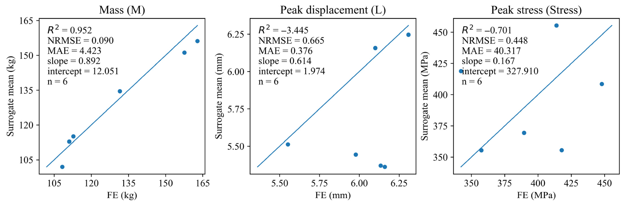
Three side-by-side parity plots with surrogate posterior mean on the y-axis and FE output on the x-axis, each overlaid with a 1:1 reference line; the Mass (M, kg) panel shows six dots sitting close to the diagonal (R² = 0.952), the Peak Displacement (L, mm) panel shows moderate scatter with most points near the line, and the Peak Stress (MPa) panel shows wide deviation from the diagonal with a near-flat point cloud (R² = −0.701) — making the relative prediction difficulty of the three responses immediately visible in a single glance. Figure A3 from: Desheng Zhang, Jieguo Liao, Longbin Wang, Zhenxin Sun, Han Zhang. "Uncertainty-Aware Lightweight Design of CFRP Battery Enclosure Under Extreme Cold Side-Pole Impact via Bayesian Surrogates." Batteries 2026, 12, 61. https://doi.org/10.3390/batteries12020061 — © 2026 by the authors. Licensed under CC BY 4.0 (https://creativecommons.org/licenses/by/4.0/).
Our perspective
None of this undercuts the contribution — it sharpens it. The honest separation of "screening" from "sign-off," and the explicit C12 failure, are exactly what make the methodology trustworthy rather than oversold.
The takeaway
The paper demonstrates a traceable, uncertainty-aware route to lightweight CFRP enclosure design under extreme cold, on a fixed budget of 50 FE runs, with a probability-of-feasibility gate doing the work that a brittle deterministic stress check could not. It shows that intrusion is learnable from sparse data while peak stress is not, that the feasible design space can split into interpretable regimes, and that one borderline candidate (C12) really does fail when you check it honestly.
For anyone building toward GB 38031-2025 with composites, that is a usable template: explore cheaply and probabilistically, then verify the few designs that matter with full simulation — and, in our view, pair that loop with a manufacturing process precise enough to build what the loop chooses.
Read the Research
Desheng Zhang, Jieguo Liao, Longbin Wang, Zhenxin Sun, Han Zhang. "Uncertainty-Aware Lightweight Design of CFRP Battery Enclosure Under Extreme Cold Side-Pole Impact via Bayesian Surrogates." Batteries 2026, 12, 61. https://doi.org/10.3390/batteries12020061
Learn More
Get in touch to discuss your CFRP enclosure AFP application →
Contact Us for a ConsultationReferences
- Desheng Zhang, Jieguo Liao, Longbin Wang, Zhenxin Sun, Han Zhang. "Uncertainty-Aware Lightweight Design of CFRP Battery Enclosure Under Extreme Cold Side-Pole Impact via Bayesian Surrogates." Batteries 2026, 12, 61. https://doi.org/10.3390/batteries12020061
- Open access, published 13 February 2026 by MDPI under the Creative Commons Attribution (CC BY 4.0) license (https://creativecommons.org/licenses/by/4.0/). All figures referenced above are © 2026 by the authors and used under CC BY 4.0; figure descriptions and ASCII visualizations in this post are Addcomposites' own renderings of the paper's data and concepts.
- Regulatory context on GB 38031-2025 drawn from public reporting, including TÜV Rheinland and Chinese government summaries of the standard's 1 July 2026 implementation.
- This article summarizes and interprets independent academic research. The study's authors are not affiliated with Addcomposites and have not endorsed this post or any Addcomposites product.
- Addcomposites. AFP-XS Automated Fiber Placement System. https://www.addcomposites.com/afp-xs
