CFRP That Carries Current as Well as Load: The Defense Aircraft Weight Penalty Hiding in Plain Sight

A modern combat aircraft can be more than a third composite by weight, yet almost none of that structure does any electrical work. The wiring that powers avionics, sensors and actuators still travels through dedicated metal — and that metal, plus the hardware needed to keep it physically separated from the surrounding composite, is one of the last large weight penalties that structural lightweighting has never touched.
A December 2025 open-access paper in Designs (MDPI), authored by Muhammad Hijaaj Tahir, Catherine E. Jones and Robert Ian Whitfield of the University of Strathclyde, sets out to change that. It presents what the authors describe as the first design-and-selection methodology for multifunctional carbon fibre-reinforced polymer (MF-CFRP) that carries mechanical load and conducts current at the same time. In this post we walk through what the paper actually proposes, where its boundaries lie, and — separately, as our own editorial view — why automated fibre placement is the manufacturing capability that turns this concept into hardware.
Throughout, we keep a clear line between what the paper shows and Addcomposites' own analysis.
The weight tax nobody budgets for
The paper opens from a familiar premise: composites already dominate airframes. The authors note that more than half of a state-of-the-art aircraft's structure is CFRP, and they put the case for the material in blunt comparative terms — where aluminium offers about 572 MPa at a density of 2.81 g/cm³, PAN-based CFRP delivers roughly 2,572 MPa at a far lighter ~2.25 g/cm³. That gap, they note, underpins savings on the order of a fifth of airframe mass against an equivalent aluminium build.
The problem, the paper argues, is that this structure is electrically dead. Because carbon fibres conduct but the surrounding resin insulates, CFRP aerostructures are normally isolated from the aircraft's electrical power system (EPS). Instead of letting the structure double as a current path the way a metal fuselage can, designers bolt on dedicated metallic bonding and grounding networks plus separated cable harnesses. The authors quantify the cost from the literature: on a Boeing 787-class aircraft, the added current-return hardware runs to at least 340 kg, and the gear that holds wiring clear of the composite can swell harness mass by roughly a third.
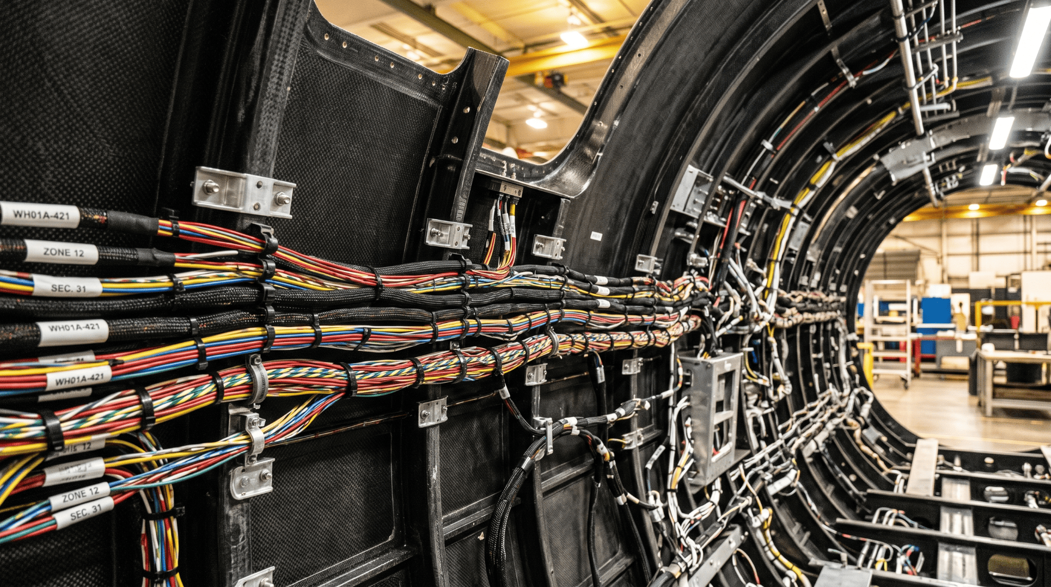
Aircraft wiring harnesses routed along carbon fibre-reinforced polymer fuselage panels, showing metallic separation brackets and multi-loom cable bundles during assembly. AI-generated illustration.
That tax is most painful exactly where weight matters most. Reviews in the wider literature put composite content of the F-35 airframe at roughly 35% by weight (per a survey in Polymers, PMC). And the conductivity problem already forces a related compromise on the skin: since CFRP doesn't shed a lightning strike the way aluminium does, carbon fibre aircraft are typically given an extra conductive layer — often an embedded metal mesh — purely for protection, adding mass that again eats into the savings the composite was meant to deliver (Sage Zander). For weight-critical military platforms and UAVs, where every kilogram trades directly against range, endurance and payload, the EPS budget is a target worth attacking.
Why CFRP refuses to conduct (in most directions)
The core technical obstacle is anisotropy. The paper explains that current essentially follows the fibres: jumping from one fibre to its neighbour within a layer, or from layer to layer, barely happens. The numbers the authors gather make the scale of the imbalance concrete.
Diagram A — Electrical anisotropy of unidirectional [0°] CFRP
Original ASCII visualization by Addcomposites. Data values from: Tahir, M.H.; Jones, C.E.; Whitfield, R.I. "A Methodology for the Design and Selection of Multifunctional Carbon Fibre-Reinforced Polymer for Aircraft Structures." Designs 2025, 9, 146, p. 3. https://doi.org/10.3390/designs9060146 — © 2025 by the authors. Licensed under CC BY 4.0. This diagram is an independent rendering, not a reproduction of any paper figure.
Carbon Fibre Electrical Conductivity — Directional Anisotropy
Conductivity varies by up to ~30,000× depending on measurement direction
Bar lengths are log-scaled for readability. Values span ~10 orders of magnitude from fibre axis to epoxy matrix.
In other words, a laminate can be an excellent conductor in one direction and almost an insulator at right angles to it. According to the authors, that behaviour can be steered: packing in more fibre (a higher fibre volume fraction, V_f) squeezes out resin and opens up fibre-to-fibre conduction paths — better electrically, but it can cost the laminate the strength that relies on that resin. This is the trade-off that sits at the heart of the whole paper, and the reason the authors insist on treating mechanical, electrical and thermal behaviour together rather than one at a time.
The Joule-heating trap
There is a second, less obvious constraint. Pushing current through a resistive material generates heat, and CFRP heats unevenly. The paper notes that even modest power — it cites an example as low as 30 W — can be enough to push a local hotspot past the resin's glass-transition point (T_g); once a laminate crosses that line, its mechanical properties begin to fall away. The hottest spots tend to be at the electrode contacts, where current crowds into a small cross-section.
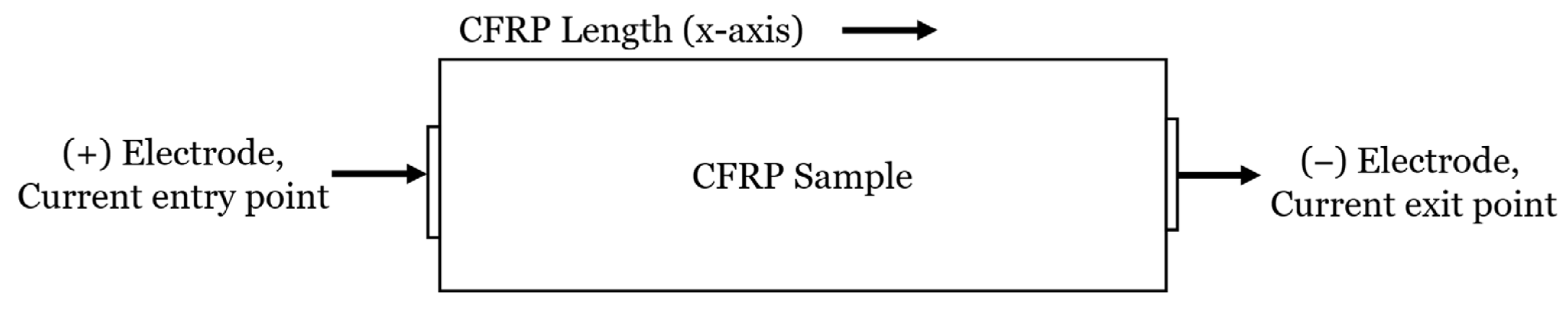
End-to-end electrode configuration for a CFRP sample, showing current entry (+) at the left end and current exit (−) at the right, with the x-axis marking sample length. Figure 7 from: Tahir, M.H.; Jones, C.E.; Whitfield, R.I. "A Methodology for the Design and Selection of Multifunctional Carbon Fibre-Reinforced Polymer for Aircraft Structures." Designs 2025, 9, 146, p. 15. https://doi.org/10.3390/designs9060146 — © 2025 by the authors. Licensed under CC BY 4.0.
So a viable MF-CFRP component has to satisfy two ceilings at once: a maximum allowable electrical resistance (set by the EPS voltage-drop budget) and a thermal limit (the resin must stay comfortably below T_g). The authors fold both into the methodology rather than checking them in isolation — a point worth keeping in mind, because the case study later runs straight into it.
A five-phase methodology, with escape hatches
The heart of the paper is a structured workflow that moves from system requirements down to a manufacturable laminate, backed by four databases (ply orientations, stacking-sequence design rules, measured electro-thermal response, and available commercial CFRP options). What distinguishes it from classical material-selection charts, the authors argue, is that it is built for a design space where no first attempt is likely to work — so every phase has an iteration loop that can either retune the laminate or push back on the system-level requirements.
Diagram B — The five-phase MF-CFRP methodology
Original ASCII schematic by Addcomposites, summarizing the phase structure described in: Tahir, M.H.; Jones, C.E.; Whitfield, R.I. "A Methodology for the Design and Selection of Multifunctional Carbon Fibre-Reinforced Polymer for Aircraft Structures." Designs 2025, 9, 146, pp. 6–23 (Figs. 1–15). https://doi.org/10.3390/designs9060146 — © 2025 by the authors. Licensed under CC BY 4.0. This diagram is an independent rendering, not a reproduction of any paper figure.
CFRP Multifunctional Design Methodology — 5-Phase Process
Forward flow with iterative feedback loops at each phase transition
A few of the equations the paper uses are worth surfacing, because they show how the design ceilings get turned into numbers. The maximum permissible resistance follows from the rated voltage, rated current and the allowable voltage-drop percentage. The component's actual resistance is modelled as a length term plus the entry/exit contact resistance, written as R_CFRP = (m × l) + R_io. Steady-state temperature against applied current is fitted as a quadratic, T_s = a·I² + b·I + c, drawn from the authors' own experimental data. And the required longitudinal conductivity comes from σ = l / (R_i × A).
The methodology was checked through a structured expert review rather than a field trial. The authors report that two specialists from the National Manufacturing Institute Scotland — one with around 15 years in composite materials, one with about 8 years in laminate processing — assessed each phase via presentation and a Likert-scale questionnaire, and that their feedback drove specific revisions (for example, adding a symmetry guideline to reduce warping, and rewording the stacking-sequence step to keep mechanical and electrical properties in balance). The experts also suggested adding cost, manufacturing rate and data-driven modelling; the paper notes these were deferred because the supporting datasets don't yet exist.
What the four databases actually hold
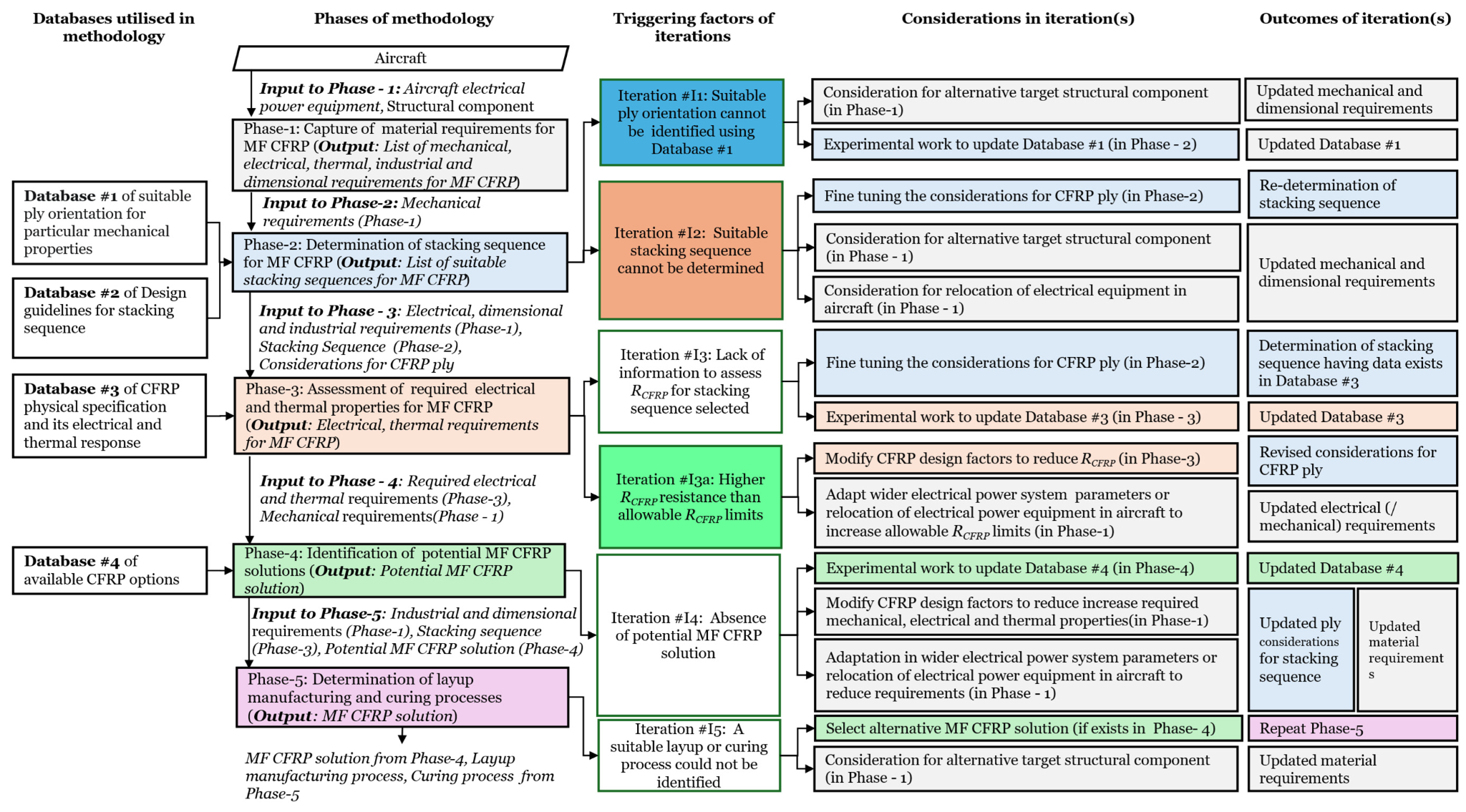
High-level block diagram of the five-phase MF-CFRP design and selection methodology, with four supporting databases (DB#1–DB#4) shown on the left feeding into their respective phases, and five iteration loops with triggering conditions and outcomes listed in the adjacent columns. Figure 1 from: Tahir, M.H.; Jones, C.E.; Whitfield, R.I. "A Methodology for the Design and Selection of Multifunctional Carbon Fibre-Reinforced Polymer for Aircraft Structures." Designs 2025, 9, 146, p. 7. https://doi.org/10.3390/designs9060146 — © 2025 by the authors. Licensed under CC BY 4.0.
The workflow only works if there's something to look things up in, and the paper is unusually frank that those reference datasets are both the engine and the bottleneck. It leans on four databases, each feeding a different phase:
Database #1 — Ply orientations for mechanical targets
Maps component shapes to recommended fibre angles. For flat panels, the authors list 0° orientations for tensile, compressive and flexural strength and for interlaminar shear; for cylindrical tubes, different angle families for axial versus radial loading. It leans on non-woven fabric on purpose — woven cloth crimps the fibres, and that crimp bleeds away stiffness.
Database #2 — Stacking-sequence design rules
Drawn from the MIL-HDBK-17 handbook, this is the set of "design rules" that keep a laminate sane: the 10% rule for orientation diversity, symmetry and balance to avoid coupling, limits on consecutive same-angle plies, damage-tolerance placement, and a guideline capping the angle between adjacent plies.
Database #3 — Measured electro-thermal response
The heart of the method, and its weakest link. It links a laminate's makeup — fibres, matrix, additives, ply stacking, electrode setup — to two measured outputs: electrical resistance and operating temperature. The authors are explicit that this is experimentally populated and sparse — which is precisely why the case study had to stay on a [0/90] layup for which data existed.
Database #4 — Available CFRP options
A catalogue of real prepregs and material systems with their mechanical, electrical and thermal properties, used in Phase 4 to match requirements to something buyable. Tellingly, several cells in the published example carry a question mark — the electrical and thermal columns are frequently empty, reflecting how rarely suppliers publish those numbers.
That last detail is, in our reading, the single most useful thing the paper surfaces: the multifunctional design space is gated less by physics than by missing measurements.
The case study: a floor-beam that doubles as a cable
To show the workflow end to end, the paper presents a deliberately illustrative case: take a wire — a 28 V DC line carrying 30 W to an avionics system — and let a structural CFRP floor-beam in the fuselage do the carrying instead. The authors are explicit that this is a demonstration of decision-making, not an optimised production part.
The setup, as described in the paper: a rated current of 1.07 A; a beam sized from representative Boeing 787 geometry at 4.5 m × 0.05 m × 0.004 m; and a 3.5% voltage-drop allowance defined by FAA AC 43.13-1B, which pins the resistance ceiling at 915 mΩ. Phase 2 produced a [0/90]₁₆ layup in PAN fibre and epoxy at 0.125 mm ply thickness.
Then the thermal/electrical reality bit — and the iteration loop earned its place:
Diagram C — Driving R_CFRP under the 915 mΩ ceiling (case-study iteration)
Original ASCII visualization by Addcomposites. Case-study values from: Tahir, M.H.; Jones, C.E.; Whitfield, R.I. "A Methodology for the Design and Selection of Multifunctional Carbon Fibre-Reinforced Polymer for Aircraft Structures." Designs 2025, 9, 146, pp. 24–26 (Section 5). https://doi.org/10.3390/designs9060146 — © 2025 by the authors. Licensed under CC BY 4.0. This diagram is an independent rendering, not a reproduction of any paper figure.
RCFRP Optimisation — Stepwise Reduction to Allowable Ceiling
Three design changes bring resistance from 3,300 mΩ down below the 915 mΩ limit
What the sequence illustrates, in the authors' framing, is the methodology's preference order: exhaust the low-disruption, laminate-level moves first (here, enlarging the electrode contact area), and only then reach into the wider system. Bumping the supply to 45 V was on the table but discarded — it doesn't line up with standard bus voltages; shortening the conduction path by relocating equipment did the job instead. To protect the beam's structural role, the authors describe keeping it as a single continuous member and carving out a 2.75 m stretch as the live conducting zone, fed by internal electrodes and isolated from the dormant section.
Diagram D — Continuous floor-beam with an embedded electrically active region
Original ASCII schematic by Addcomposites, redrawn to convey the configuration in Figure 16 of: Tahir, M.H.; Jones, C.E.; Whitfield, R.I. "A Methodology for the Design and Selection of Multifunctional Carbon Fibre-Reinforced Polymer for Aircraft Structures." Designs 2025, 9, 146, p. 26. https://doi.org/10.3390/designs9060146 — © 2025 by the authors. Licensed under CC BY 4.0. Redrawn and simplified; not a reproduction of the original figure.
Conduction Path Optimisation — Equipment Relocation Strategy
Reducing the active electrical path from 4.5 m to 2.75 m by repositioning the power converter
Phase 4 matched the resulting targets to a real product, identifying IM7-8552 prepreg as meeting the combined mechanical, electrical and thermal requirements. And in Phase 5, the paper states, the case study's manufacturing pick for a flat part that lives or dies on orientation accuracy was automated fibre placement, chosen as the route for both laying down and curing the laminate.
Where the paper draws its own boundaries
A strength of this work is that the authors are candid about its limits, and we think any honest summary has to carry those forward. The paper acknowledges that its reach is gated by the data behind Database #3 — the experimentally measured electro-thermal responses. In practice that meant the case study used a [0/90] configuration to stay on solid data, even though the design rules generally favour keeping the angle between adjacent plies at or below 45°; the electro-thermal datasets for ±45° layups simply aren't there yet.
The authors also note that the present version only holds where the current is direct or low-frequency alternating — the regime in which CFRP acts as a plain resistor — and does not yet handle the high-switching-frequency power electronics where skin effect and frequency-dependent impedance start to matter. EMI shielding, lightning-strike protection, long-term durability (moisture, UV, repairability), production rate, cost and certification timelines are all named as out of scope for this early-stage, technically focused version — and flagged as future work, including possible use of FEA and machine learning to fill data gaps. Read fairly, the contribution is a decision framework and a map of what's missing, not a finished design tool.
Our perspective: why this lands on AFP
The following is Addcomposites' own analysis. The paper's authors have not reviewed or endorsed this commentary, our products, or our company.
Two things in this paper stand out from a manufacturing standpoint.
First, the design window the methodology defines is fundamentally a stacking-sequence and fibre-volume-fraction window. The methodology's whole premise is that electrical and thermal behaviour are governed by ply orientation, ply count, V_f and electrode geometry — the same variables that govern mechanical performance, only now they have to be hit simultaneously. A laminate that meets a 915 mΩ ceiling at one electrode width and one path length is sensitive to exactly the parameters that vary most with manual layup. That sensitivity is, in our view, the practical case for automated fibre placement: repeatable, ply-by-ply orientation and consistent V_f are not a nice-to-have for multifunctional parts — they are the difference between a laminate that conducts to spec and one that doesn't.
Second, the paper's own demonstrator landed on AFP as the manufacturing route. We read that as confirmation of where this class of part naturally sits, not as any endorsement of a vendor.
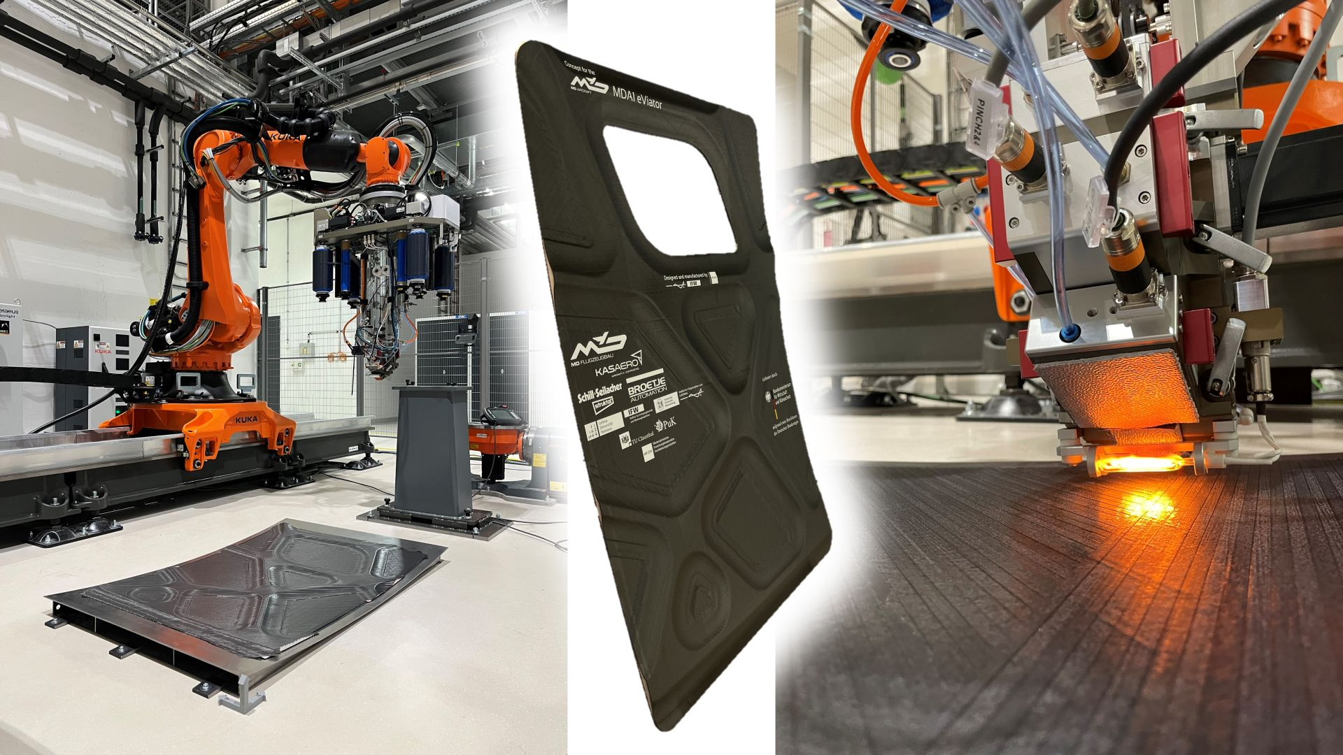
Topology-optimized carbon fibre fuselage structure manufactured on a flat tool using Addcomposites' AFP-X system (left), the finished structural part (centre), and a close-up of the AFP-X head during active tow placement (right). Image credit: IFW, Leibniz Universität Hannover.
This is the space our systems are built for. The AFP-XS, AFP-X and ADDX platforms place fibre with the orientation and volume-fraction control that a multifunctional laminate demands, and AddPath lets teams plan and verify those stacking sequences before a single ply is laid. For defense AFP users producing structural panels and beams today — purely for mechanical performance — this methodology is a prompt to open a conversation with OEM structural and electrical teams about laminates that also carry power, and to start capturing the electro-thermal data the paper identifies as the field's main gap.

AddPath's layup simulation interface showing ply-by-ply tape sequencing and robot path verification on a flat panel geometry.
There's a first-mover dimension here worth naming plainly. Because Database #3 and Database #4 are so thin, whoever generates trustworthy electro-thermal data for production-representative layups effectively defines the usable design space for everyone who follows. A defense supplier already running AFP at production quality is in an unusual position to do exactly that: the same machine that lays the structural part can lay the characterization coupons, with the orientation and V_f consistency that makes the resulting measurements meaningful rather than noise. In a procurement environment where weight, range and survivability are scored hard, the ability to offer a structural panel that also retires part of the EPS mass budget is not a marketing line — it's a measurable trade against payload. The methodology gives that conversation a defensible technical spine; AFP gives it a path to repeatable hardware.
It's worth distinguishing this from the parallel structural-battery thread in defense R&D — efforts like the DoD's structural energy-and-power work and the EU's SOLIFLY project, where composites store energy. There, the laminate is engineered to hold charge as well as bear load (CompositesWorld). The Strathclyde methodology is about conducting current, not storing it — a nearer-term, lower-risk step on the same road toward higher EPS power density. Both point the same way: structure that does electrical work.
Read the research
This post summarizes and comments on the following open-access article. We encourage reading the original in full.
Tahir, M.H.; Jones, C.E.; Whitfield, R.I. "A Methodology for the Design and Selection of Multifunctional Carbon Fibre-Reinforced Polymer for Aircraft Structures." Designs 2025, 9, 146. https://doi.org/10.3390/designs9060146
© 2025 by the authors. Published by MDPI under the Creative Commons Attribution (CC BY 4.0) license (https://creativecommons.org/licenses/by/4.0/).
Supporting context drawn from external sources: composite content of military airframes (PMC, "Practical Use of Composite Materials Used in Military Aircraft"); lightning-protection mass penalty on CFRP skins (Sage Zander); and the structural-battery comparison (CompositesWorld coverage of the SOLIFLY project). These are cited for background only and are independent of the Strathclyde paper.
Learn More
Get in touch to discuss your multifunctional CFRP or AFP manufacturing application →
Contact Us for a ConsultationReferences
- Tahir, M.H.; Jones, C.E.; Whitfield, R.I. "A Methodology for the Design and Selection of Multifunctional Carbon Fibre-Reinforced Polymer for Aircraft Structures." Designs 2025, 9, 146. https://doi.org/10.3390/designs9060146
- PMC. "Practical Use of Composite Materials Used in Military Aircraft." Polymers review series.
- Sage Zander. Lightning-protection mass penalty on CFRP aircraft skins. Industry reference.
- CompositesWorld. Coverage of the SOLIFLY project (structural-battery composites, EU defense R&D). https://www.compositesworld.com
