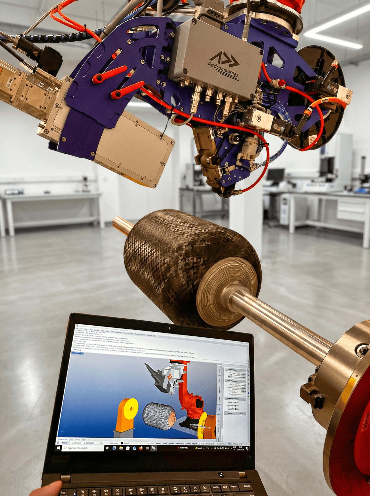
From Design to Cost Estimate in Minutes: What a New CFRP Framework Tells Us About the Future of AFP
There's a problem that anyone who has ever quoted an aerospace composite job knows intimately: the structural engineer changes a ply orientation on Thursday, and by Friday, the manufacturing cost estimate is already wrong. Not slightly wrong — potentially thousands of euros wrong — because no one has had the time to re-run the lay-up sequence, recalculate draping time, re-estimate autoclave cycles, or reprice material waste.
This is not an AFP problem or a hand lay-up problem. It is a data architecture problem. Design and manufacturing have been living in separate silos, speaking different languages, for decades.
A paper published in March 2026 in Aerospace (MDPI) by Claudia Schopper, Dominik Schopper, Maximilian Holland, Julian Dinkelacker, Julian Schuster, and Stephan Rudolph — titled "Model-Based Engineering Process Automation from Design to Manufacturing of Fiber Composite Helicopter Structures Using Graph-Based Design Languages" — proposes a concrete, working answer. And its implications for how AFP operators plan, quote, and sell are worth unpacking carefully.
The Problem They Set Out to Solve
The paper, which comes out of the COBAIN research project, a collaboration between the University of Stuttgart, IILS mbH, Fraunhofer IGCV, and Airbus Helicopters Deutschland (AHD), begins with a description of the situation most composites engineers will recognize: The paper notes that "the highly customized and often complex geometries of components can lead to process-related defects and quality variations. Consequently, many manufacturing steps still rely heavily on manual labor, making cost estimation and reproducibility difficult."
The diagnosis cuts deeper, though. It isn't just that manufacturing is hard. It's that the data flow between design and manufacturing is broken. As the authors put it: "Fragmented toolchains and isolated disciplines often lead to breaks in data flow and hinder the evaluation of how design choices affect manufacturing effort, recurring costs, or material efficiency."
The Core Issue
Every time a design changes — a frame profile shifts from an I-section to a C-section, a ply stack is reordered, an autoclave curing cycle is revised — someone on the manufacturing planning side has to rebuild their estimate from scratch. At large programs, this means specialized cost engineers. At smaller shops, it often just doesn't happen. Quotes go out on stale assumptions. Margins erode. Schedules slip.
What a Graph-Based Design Language (GBDL) Actually Does
The research team's solution is built around a concept called a Graph-Based Design Language (GBDL). If you haven't encountered the idea before, it's worth spending a moment on, because it's more intuitive than the name suggests.
Think of a conventional CAD model: it stores geometry. Think of a conventional FEM file: it stores loads and material properties. Think of a manufacturing planning spreadsheet: it stores process times and costs. Each of these lives in its own file format, on its own software, managed by its own specialist. Moving data between them involves exports, imports, manual re-entry, and — inevitably — errors and version conflicts.
A GBDL replaces this with a design graph: a single, unified data model where geometry, material, tooling, and process parameters are all nodes and edges in the same connected structure. The graph is not just a storage format; it is an executable one. Rules encoded in the graph can automatically derive new information from existing nodes — for example, computing draping time from a ply's surface area and curvature, or generating a robot trajectory from a set of guide curves.
.png)
Figure 14: Design graph of an AFP component showing plies, zones, tool surface, and reference curves. From Schopper et al., Aerospace 2026, 13, 311. https://doi.org/10.3390/aerospace13040311 CC BY 4.0. [Cropped/resized from original.]
Unified Design Graph
Integrated pipeline linking geometry, structural analysis & manufacturing planning to automated cost evaluation
The Helicopter Frame Case Study
The research team demonstrated the approach on a CFRP helicopter fuselage frame — exactly the kind of component that makes manual cost estimation painful: curved, structurally critical, available in multiple profile variants (I, C, and Ω cross-sections), and subject to revision throughout the design cycle.
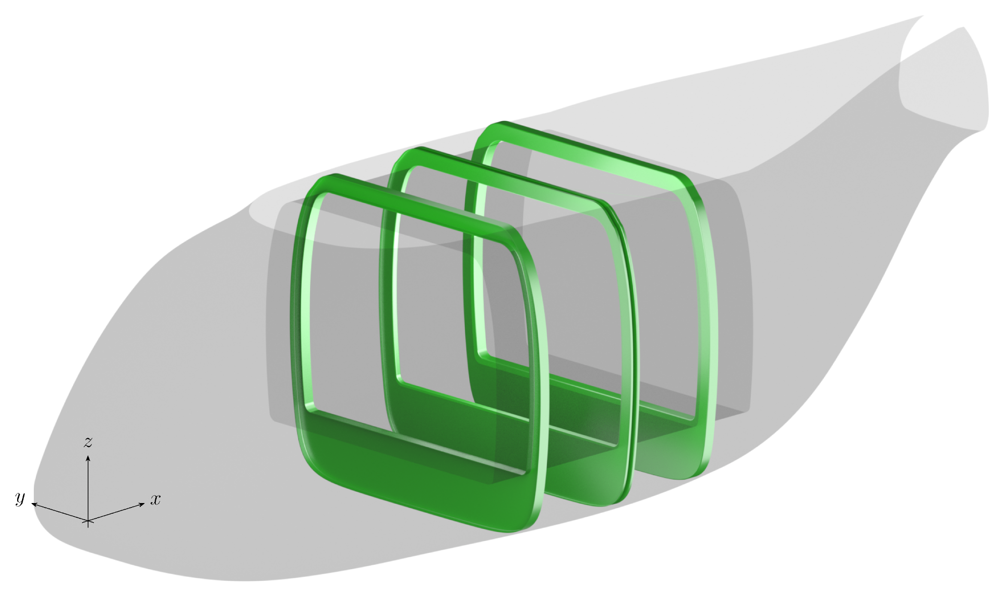
Figure 6: Different variants of helicopter frames (I, Omega, C profiles) at different positions within the fuselage geometry. From Schopper et al., Aerospace 2026, 13, 311. https://doi.org/10.3390/aerospace13040311. CC BY 4.0. [Cropped/resized from original.]
The three profile types they modeled each have their own geometric parameters, but share a common parent class and general design logic. In plain terms: the system knows the rules for all three, and can generate a fully detailed CAD model for any of them — automatically — from just a frame position along the fuselage x-axis and a chosen profile type.
Frame Profile Types
Parametric cross-section geometries used in AFP frame path planning — hover parameter chips to highlight dimensions
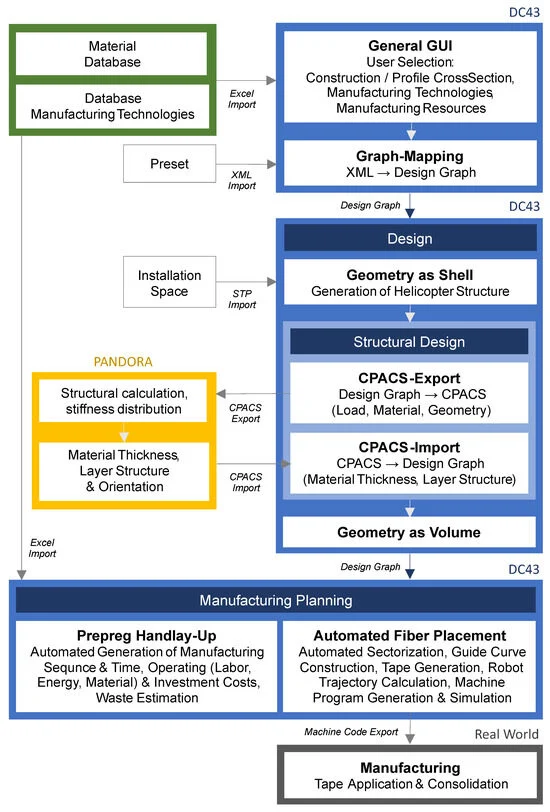
Figure 1: Schematic overview of the automated engineering process from design to manufacturing, showing applications and file exchange formats between modules. From Schopper et al., Aerospace 2026, 13, 311. https://doi.org/10.3390/aerospace13040311 CC BY 4.0. [Cropped/resized from original.]
From Selection to NC Code — Automatically
How fast does this run? According to the paper, the automated generation sequence for one complete frame — any of the three profile types — takes less than one minute on a standard mobile workstation. For comparison, generating the same geometry manually in CAD software would typically take hours, and then separately estimating manufacturing costs would take more hours still.
The design language's structural output is exported via CPACS to PANDORA, DLR's structural optimization tool, which returns optimized ply thicknesses and layer orientations. These results are automatically re-imported into the design graph, which then feeds the manufacturing planning modules.
Two Manufacturing Paths, One Integrated Model
What makes this research particularly relevant for AFP operators is that the team explicitly models both prepreg hand lay-up and automated fiber placement as parallel planning paths within the same framework — and treats them as genuine alternatives to be compared on cost, lead time, waste, and energy grounds.
Prepreg Hand Lay-Up: Embedding the Expert
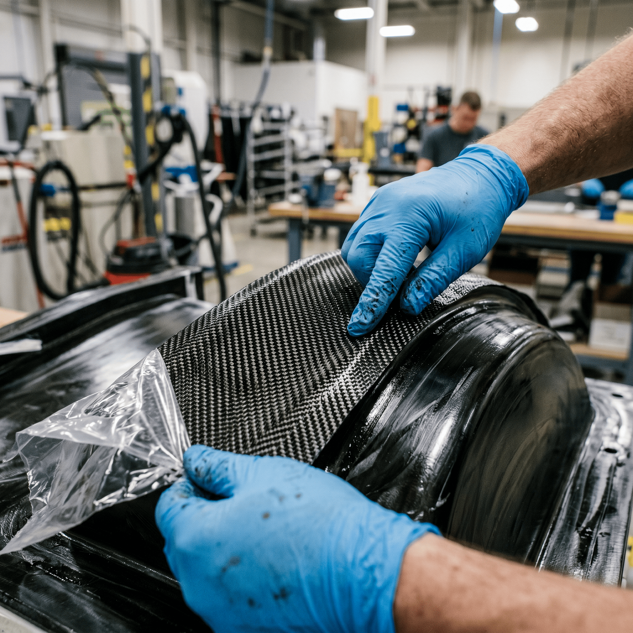
Manual prepreg layup on a curved mold tool — the process knowledge the COBAIN model encodes as empirical equations.
The hand lay-up module represents something genuinely difficult: encoding tacit expert knowledge into a machine-executable form. The model decomposes the process into main steps (cutting, laminating, compacting, curing, demolding) and sub-steps (positioning the cut piece, draping, manual cutting within laminating), and assigns empirical equations to each.
The draping time equation is a good illustration of how far this granularity goes: draping time is a function of a base time constant, the cut piece surface area, the worker's draping speed, and a complexity factor derived from the proportion of the ply that covers strongly curved areas (above 0.11/m curvature).
The system knows, automatically, that a curved ply takes longer per unit area than a flat one.
Hand Lay-Up Process Decomposition
Hierarchical process structure feeding automated lead time, labour & cost evaluation — click any step to expand
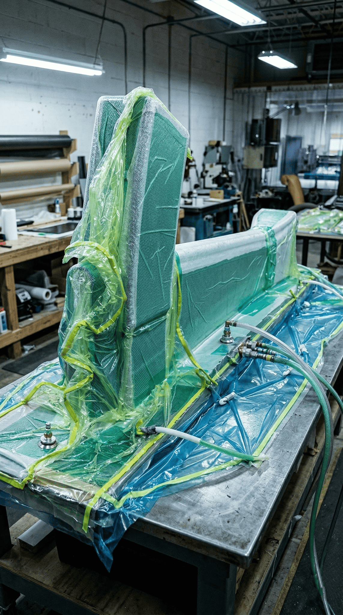
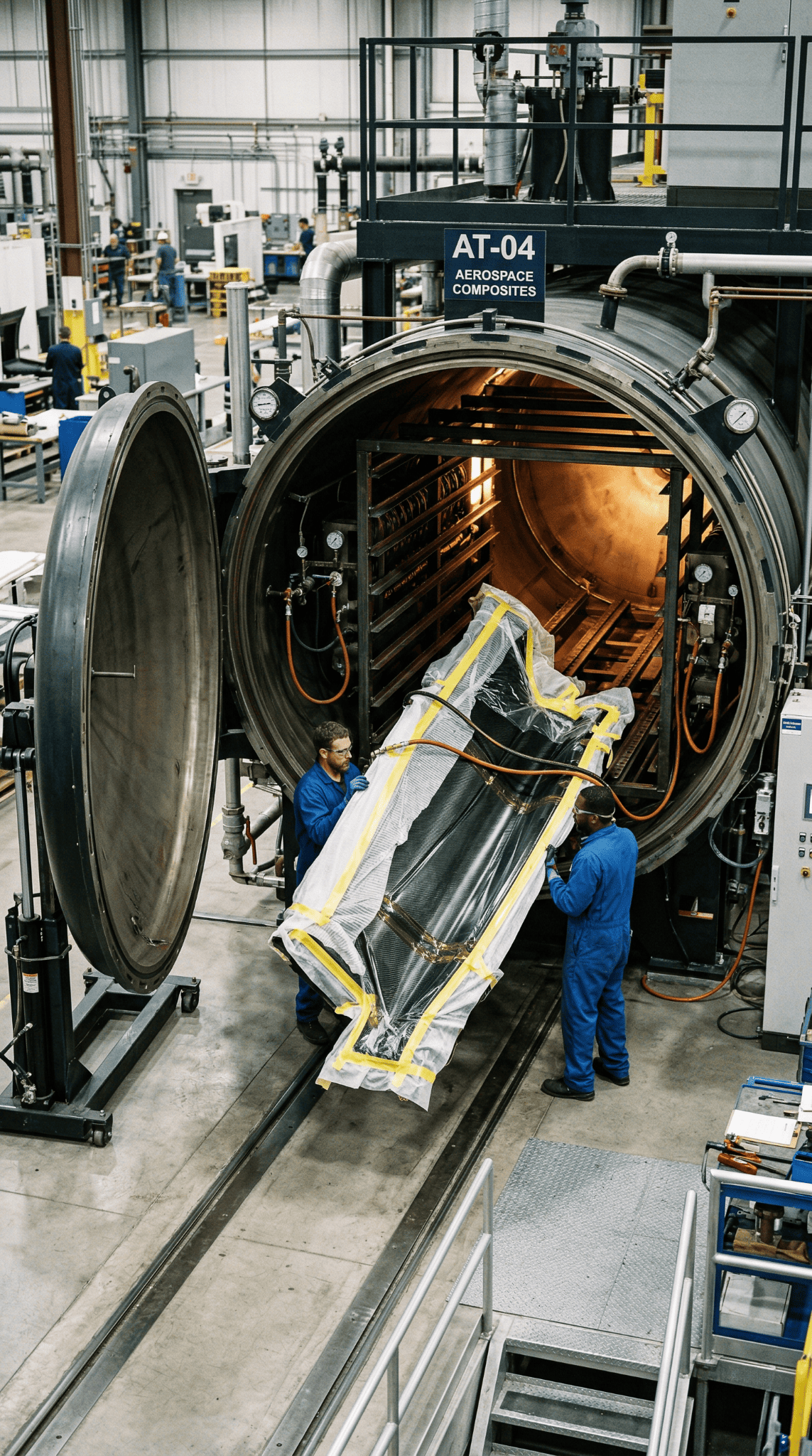
Vacuum-bagged composite layup ready for compaction and cure — the production reality the model was validated against.
The model was validated against real production data from AHD. The paper notes the predictions were qualitatively close to real-world values, with quantitative details withheld under NDA.
AFP: From Design Graph to NC Code
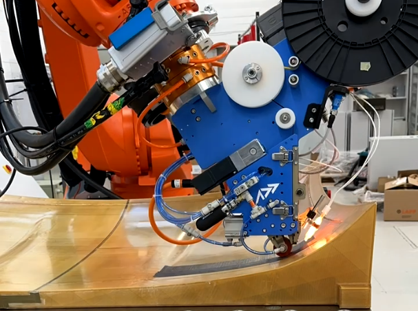
AFP-XS depositing carbon fiber tow on a curved mold — from design graph to machine execution.
The AFP module goes a step further — not just estimating manufacturing cost, but generating the actual machine control program.
The workflow moves from the design graph (DC43/GBDL) through AFP component model, sectorization and guide curve construction, and NC code generation — all the way to physical lay-up on the Coriolis C1.2 at Fraunhofer IGCV in Augsburg.
AFP Digital Process Chain
From parametric design graph to verified NC code — three integrated stages bridging CAD, path planning & machine floor
└── Plies [0°, 45°, 90°, −45°, 0°]
├── orientation (deg)
├── thickness t = 0.125 mm
└── zone → boundary wire on tool surface
+ reference curve (0° fiber dir)
The trial runs at Fraunhofer IGCV in Augsburg confirmed what the model predicted: it is possible to automatically generate machine-executable NC code from a design graph, including for multi-sector, multi-orientation lay-ups on doubly curved surfaces. This closed the loop from digital model to physical laminate without manual programming at the machine level.
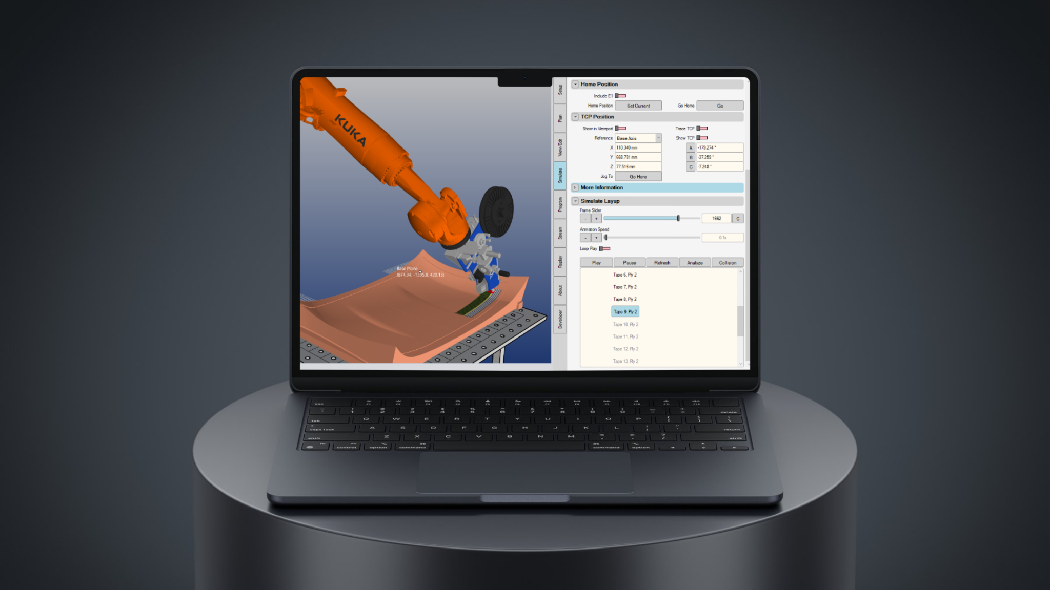
AddPath simulating AFP-XS tow paths on a curved mold — digital verification before physical layup.
Why This Matters for AFP Operators Right Now
The COBAIN research is primarily methodological — the authors are candid that large-scale empirical validation and detailed benchmarking lie outside this paper's scope. But the implications for the composites manufacturing market are already clear.
The Quoting Problem Is Solvable
Manufacturing cost, lead time, waste, and energy estimates can be computed automatically from the same data model used for structural design — provided the underlying ontology is correctly structured. This runs in under a minute on a laptop.
AFP Is the Forward Path
In the framework, AFP is not an afterthought — it is one of two first-class manufacturing methods modeled at equal depth, with its own design language producing machine code that can be sent directly to a robot.
Design Changes Become Cheap
One of the most powerful features is that, as the authors note, "the design graph retains all intermediate values" — meaning recalculations with modified parameters can be carried out rapidly without rebuilding the model from scratch. For AFP operators, this means a design change by the customer triggers an automatic cost update, not an hours-long re-estimate.
The Workflow AFP-XS Users Need
This is the workflow that AFP-XS users operating in aerospace supply chains need. The structural customer changes a frame profile from I to Ω; the AFP operator needs to know, within minutes, what that means for lay-up time, tow waste, and quote price. The COBAIN framework shows exactly how to build that capability — and the tools to execute it (AddPath for path planning, AFP-XS for deposition) already exist.
AFP-XS and AddPath in operation — the path planning and deposition tools the COBAIN framework connects to.
What Still Needs Work
The paper is honest about current limitations, and it is worth being equally direct here.
The translation of component geometry into the preforming structure (preforms, subpreforms, ply stacks) is currently still performed manually for the hand lay-up module. Automated ply derivation approaches were developed in the project but are not published. This is a significant gap: if the ply book still requires manual interpretation, the time savings are partially offset.
For AFP specifically, the sectorization rules — deciding how to partition a curved surface into lay-up sectors — are implemented as fixed algorithms. The trade-off between fiber angle deviation and gap/overlap is managed by rule, not optimized per component. More sophisticated optimization here (variable angle tow steering, for example) would require extending the design language with additional rules and, likely, integration with path planning tools like AddPath.
The framework also currently handles only monolithic structures in the structural design loop. Sandwich structures are supported in the manufacturing planning module but not yet fully connected back to the geometry and structural design languages. The authors acknowledge this and note that extension is architecturally straightforward — it requires additional ontology classes and rules, not a redesign.
The Bigger Picture
What the COBAIN project has built is a working prototype of something the composites industry has wanted for a long time: a single model of truth that spans design and manufacturing, that propagates changes automatically, and that produces actionable outputs — including machine code — without manual re-entry.
The data architecture is the innovation here, not the manufacturing process or the structural analysis method. Graph-based design languages are the plumbing. The payoff is that AFP — already the highest-performance deposition technology accessible to smaller manufacturers through systems like AFP-XS — becomes not just a production tool but a design evaluation tool. You can explore ten frame variants, compare their AFP manufacturing costs automatically, and select the best one before cutting a single piece of prepreg.
.png)
AFP-XS and a finished CFRP component represent the full chain the COBAIN framework is designed to automate — from installation space extraction to physical deposition.
For AFP operators competing on aerospace programs — whether as Tier 1 suppliers or as job shops quoting against hand lay-up incumbents — this direction of travel is significant.
The tools to implement the manufacturing side of this framework already exist: AddPath handles path planning and trajectory generation; AFP-XS handles deposition. What the COBAIN research adds is the upstream architecture that makes the full chain — from installation space to NC code — coherent and automated.
Traditional Workflow vs. GBDL-Integrated Workflow
From siloed manual handoffs taking days — to a unified design graph that propagates changes in under a minute
manual
manual
re-export hours
re-run hours
re-entry hours
(nodes)
Analysis
Planning
updates <1 min
re-evaluated <1 min
re-computed <1 min
Reading the Research
The full paper is open access and available at:
Schopper, C.; Schopper, D.; Holland, M.; Dinkelacker, J.; Schuster, J.; Rudolph, S. Model-Based Engineering Process Automation from Design to Manufacturing of Fiber Composite Helicopter Structures Using Graph-Based Design Languages. Aerospace 2026, 13, 311. https://doi.org/10.3390/aerospace13040311
The research was funded by the German Federal Ministry for Economic Affairs and Climate Action (BMWK) under the LuFo program, grant numbers 20W1908B, 20W1908D, and 20W1908E. Data are not publicly available due to confidentiality agreements with Airbus Helicopters Deutschland.
Addcomposites provides the AFP-XS fiber placement system, AddPath path planning software, and AddCell robotic cells — the manufacturing execution layer that frameworks like COBAIN are designed to connect to. If you're working on design-to-manufacture integration for CFRP aerospace components and want to understand how AFP-XS fits into a model-based engineering workflow, get in touch.
Learn More
Working on design-to-manufacture integration for CFRP aerospace components? Get in touch to discuss how AFP-XS fits into a model-based engineering workflow →
Contact Us for a ConsultationReferences
- Schopper, C.; Schopper, D.; Holland, M.; Dinkelacker, J.; Schuster, J.; Rudolph, S. Model-Based Engineering Process Automation from Design to Manufacturing of Fiber Composite Helicopter Structures Using Graph-Based Design Languages. Aerospace 2026, 13, 311. https://doi.org/10.3390/aerospace13040311
- Addcomposites. AFP-XS Automated Fiber Placement System. https://www.addcomposites.com/all-products/afp-xs
- Addcomposites. AddPath Path Planning Software. https://www.addcomposites.com/addpath
This post was prepared by the Addcomposites team. Addcomposites develops the AFP-XS automated fiber placement platform. For questions about AFP process development and model-based engineering integration, contact us at addcomposites.com.
