How to Choose the Right Robot for AFP: A Buyer's Guide
Most buyers start with the wrong question. This guide is a decision framework that starts where robot selection should start: with your composite part and process.
Most buyers start with the wrong question. "Which robot brand should I use?" or "How much payload do I need?" are reasonable questions — but they're the second question, not the first. The first question is: what does your process actually demand?
This guide is built from real conversations with AFP system users and the applications team at Addcomposites. It's not a spec sheet comparison — it's a decision framework that starts where robot selection should start: with your composite part and process.
Step One: Define Your Process Envelope
Before you open a robot datasheet, you need four things defined:
- Part geometry — flat, single curvature, double curvature, or complex
- Minimum steering radius — this defines path complexity and required wrist agility
- Placement tolerance — typically ±0.25 to ±1 mm depending on structural requirements
- Layup speed target — 100 to 600 mm/s is the typical AFP range
These aren't robot specs. They're process specs. But they map directly onto robot capability requirements: reach, payload, path accuracy, and motion control quality. Until you have this definition, any robot recommendation is guesswork.
Buyers who arrive with these defined move significantly faster through robot selection and make better decisions. Buyers who arrive without them aren't less capable — robot selection without process definition is just premature.
Payload: The Number That Catches Everyone Off Guard
Payload is the most commonly misunderstood selection criterion in AFP robot purchasing. Most buyers look at the AFP head weight and add a small buffer. That's not enough.
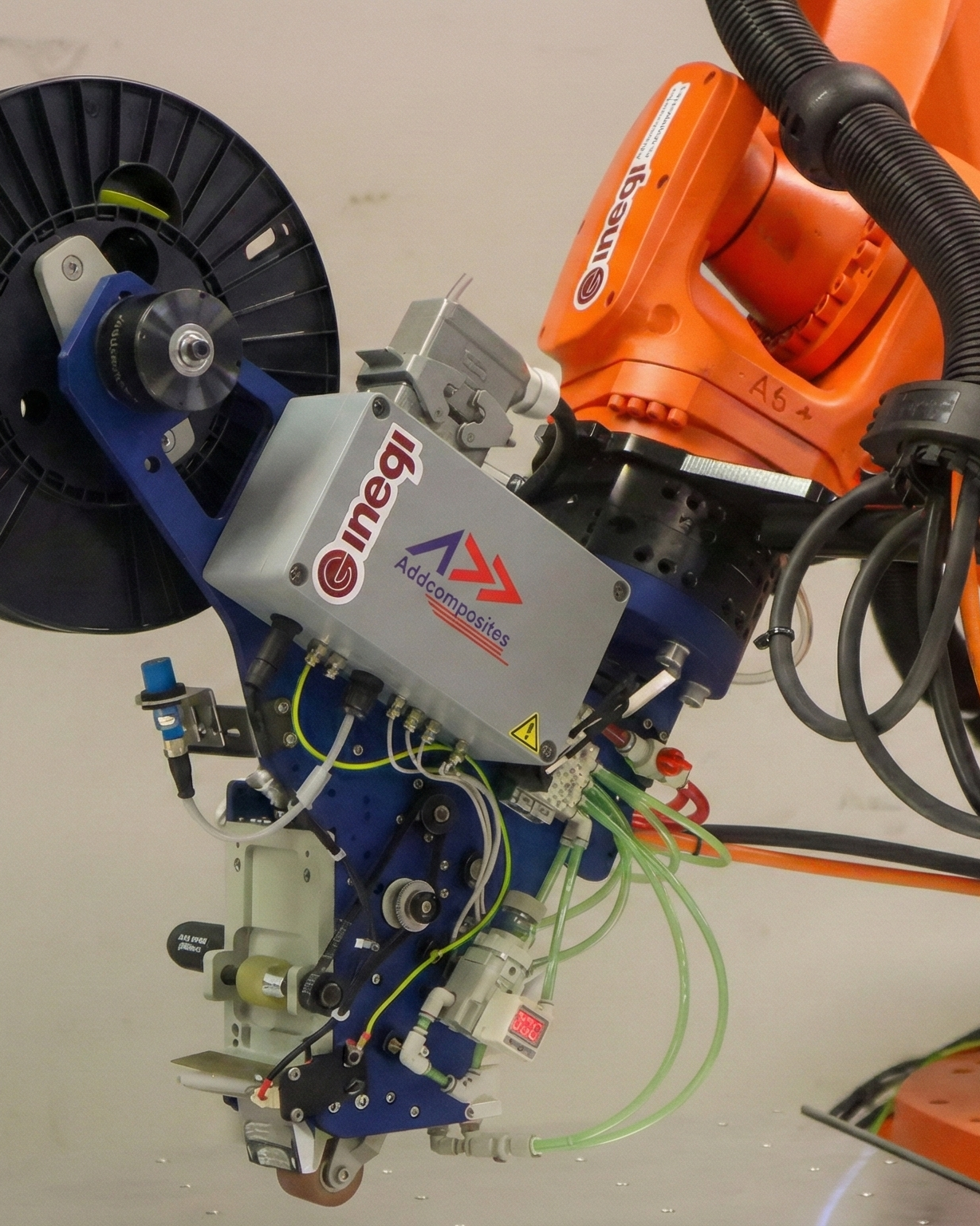
AFP-XS mounted on a KUKA robot at INEGI — fiber spool, cable management, and compaction assembly make up the real payload stack.
The Real Payload Stack
The real payload is a stack. For an AFP-XS system, the effective tool load at the wrist is approximately 36–51 kg before process forces are considered. Adding compaction and fiber tension forces (50–300 N compaction, process-dependent), the AFP-XS minimum robot requirement is 70 kg. AFP-X minimum is 250–300 kg, and AddX minimum is 70 kg.
The 70 kg minimum for AFP-XS isn't just about carrying the head — it's about having enough wrist torque to apply compaction force at the roller while maintaining path accuracy. A robot sized to carry the head may still fail dynamically: vibrating, drifting on curved paths, or running below target speed because it lacks torque margin.
Rule of Thumb
Operate at ≤60–70% of rated payload for AFP applications. The remainder isn't waste — it's your accuracy and reliability buffer.
The Wrist Torque Problem Most Buyers Miss
Here's what rarely appears in procurement conversations but matters enormously in practice: the difference between static payload and dynamic payload.
A robot rated for 70 kg can carry 70 kg in a static test. But during AFP layup, the wrist is moving continuously, pressing a roller against a surface at angles that change constantly. Two forces are working against you simultaneously:
- Compaction force — the roller pressing down on the laminate (typically 50–300 N, depending on material and process)
- Fiber tension — the pull-back force from the tow as it unspools from the creel
Both forces act through the TCP offset — the distance from the wrist flange to the roller contact point. The longer that offset, the greater the moment arm, and the more torque the wrist must resist. A 600 mm TCP offset with 200 N of combined process force creates 120 Nm of torque at the wrist before you've even accounted for tool inertia.
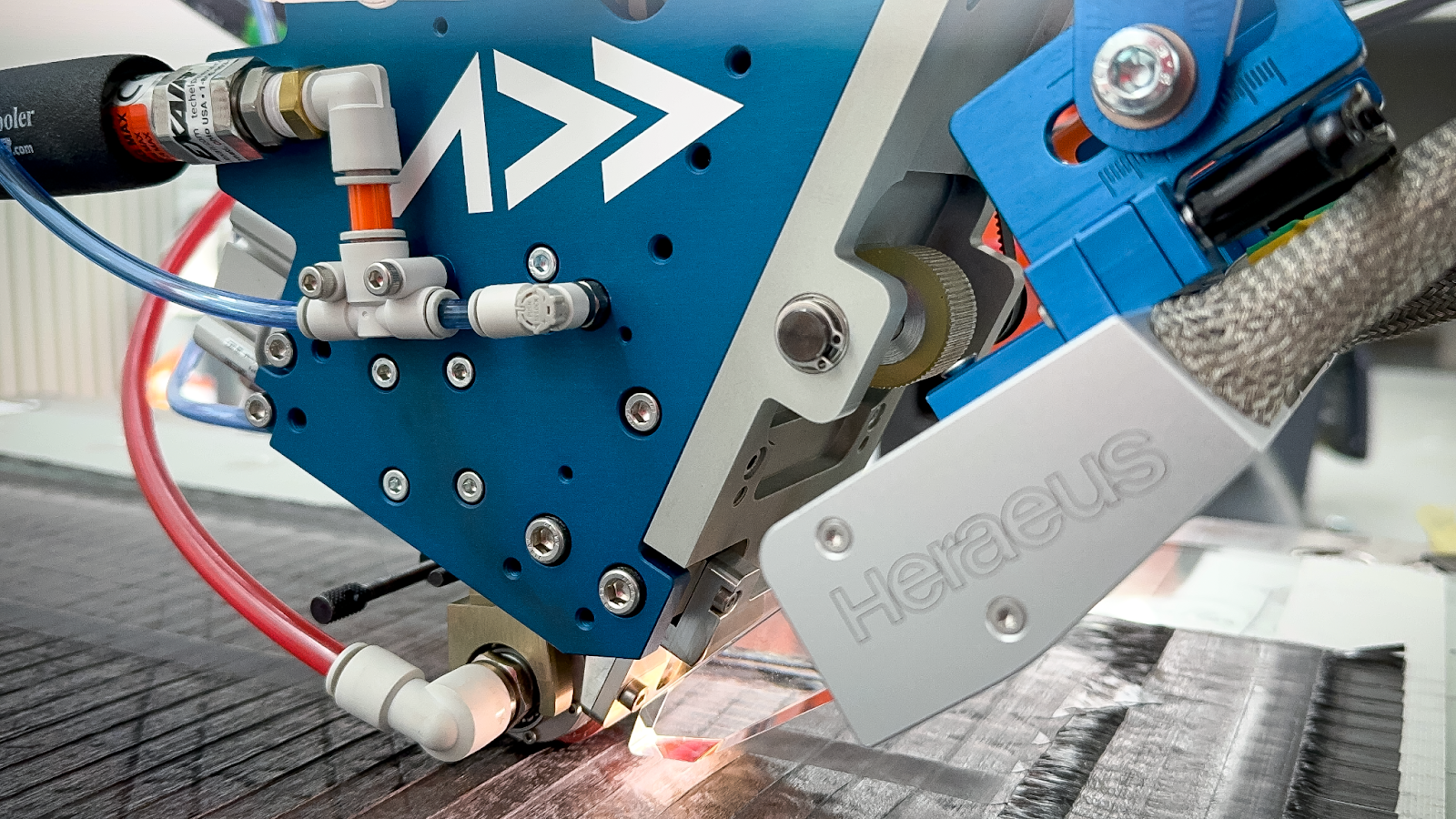
AFP-XS compaction roller in contact with carbon fiber laminate — compaction force and fiber tension act simultaneously through the TCP offset, loading the robot wrist with every pass.
This is why robots selected close to their payload limit regularly underperform in AFP applications: they pass the carry test but fail the process test. The symptom isn't a crash — it's subtle accuracy drift on curved paths, reduced achievable speed, and vibration that shows up as placement inconsistency.
Addcomposites systems are specifically designed to minimize this problem: lightweight tooling, minimal TCP offset, and compact geometry that reduces moment arm loads. This is what allows mid-range robots to perform reliably rather than requiring heavy-duty platforms.
Part Size Drives Architecture
The size of your part determines which robot configuration makes sense — not the robot model, but the entire physical arrangement of the cell.
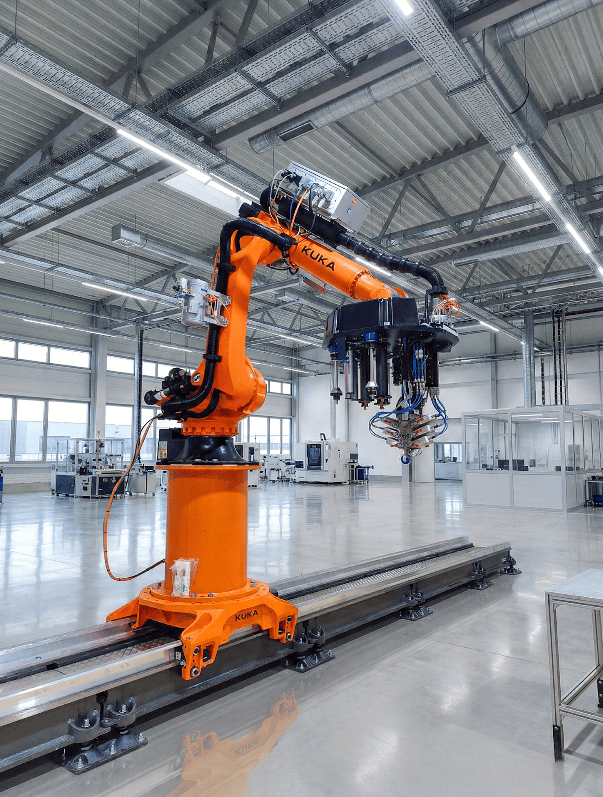
KUKA AFP-X on a linear track — when parts outgrow a fixed base, the robot travels to the part, not the other way around.
When Parts Outgrow Fixed Bases
For parts up to 2 m, a standard 6-axis robot on a fixed base is the most common and simplest starting point. As parts grow, the architecture must adapt — adding positioners, 7th-axis tracks, or in extreme cases, full gantry systems.
A word on gantries: they appear in AFP literature frequently, but they're often misapplied. A gantry is essentially a large 3D printer — fixed base, linear motion in X, Y, and Z, no rotational freedom at the tool. That makes it poorly suited for complex double-curved geometries. For most AFP applications, a robot on a linear track is both cheaper and more capable than a gantry.
Gantries make practical sense only when parts reach 30–50 m in scale, where robot-on-track systems lose accuracy as the robot travels extended distances. For anything smaller, the gantry's rigidity becomes a limitation rather than an advantage.
Robot Brands: What Field Experience Shows
Addcomposites systems are robot-agnostic by design — the software and tooling are built to work across platforms. That said, field experience across multiple deployments has produced clear patterns.
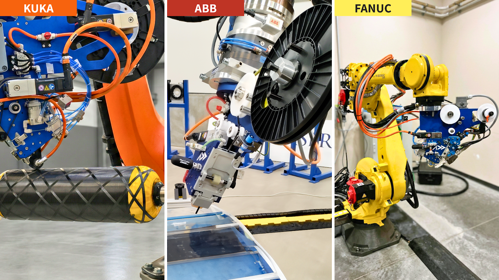
One AFP head, three robot brands — KUKA, ABB, and FANUC all run the same Addcomposites system without custom hardware.
KUKA's prevalence comes primarily from controller flexibility. AFP requires continuous path interpolation — smooth, high-rate motion control along programmed curves — and KUKA's controller architecture gives more customization options than competitors in that specific area. ABB and Fanuc are solid platforms and work well, but offer slightly less flexibility on certain motion control configurations.
On lesser-known or emerging-market robot platforms: while the purchase price can be attractive, some platforms present integration challenges around controller flexibility and AFP-specific motion control requirements. If a customer arrives with one of these systems already installed, the practical path forward depends on the specific platform — in some cases, pairing it with a gantry architecture may be a more viable route than deep controller integration work.
Path Accuracy: What the Datasheets Don't Tell You
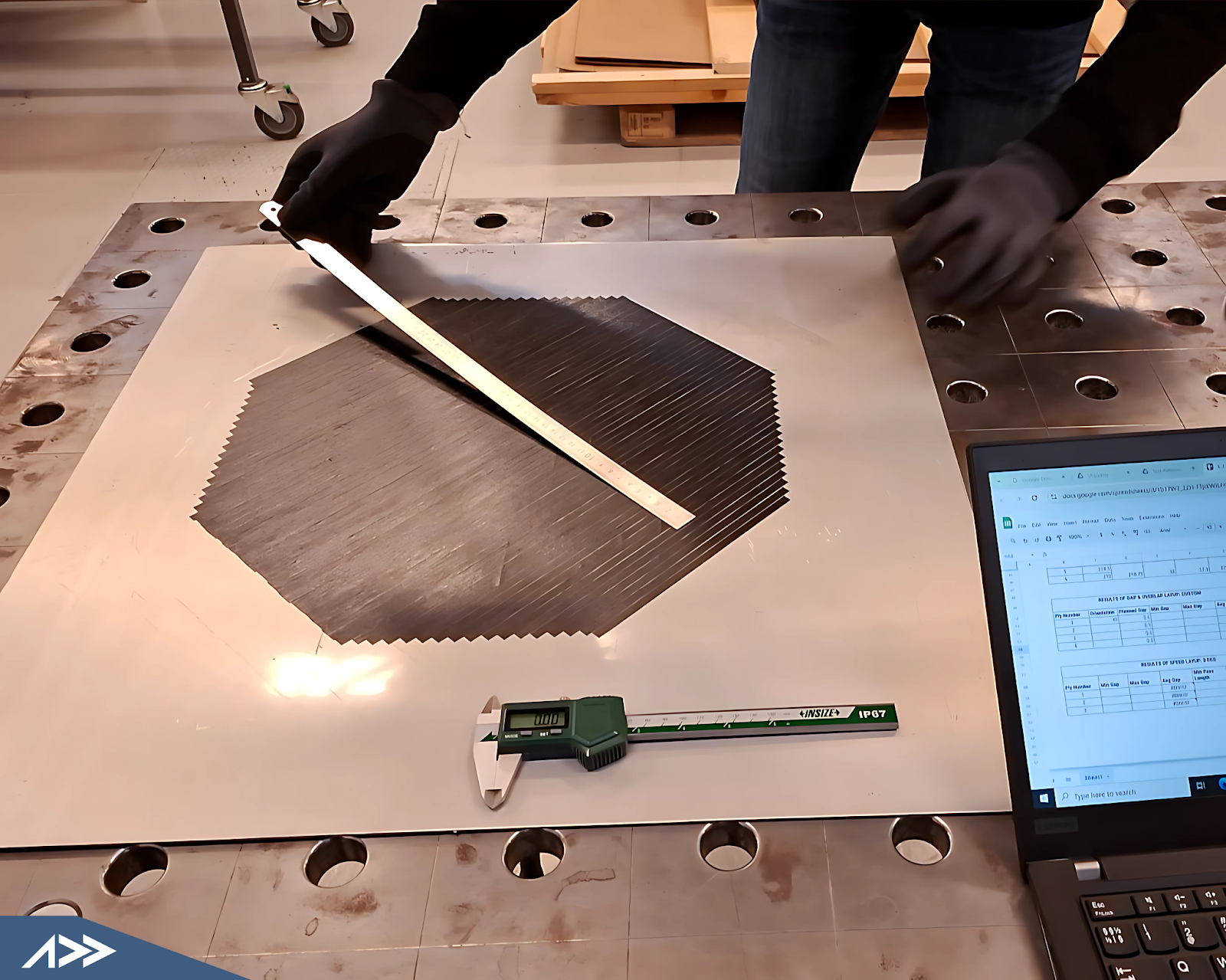
AFP requires absolute accuracy — not just repeatability. The distinction is critical and is consistently misunderstood in robot selection conversations.
A robot with ±0.05 mm repeatability and ±2 mm absolute accuracy will return to its taught position consistently — but if that taught position drifts from your programmed path, you're placing tows in the wrong location. For AFP, where tow gap and overlap tolerances are typically measured in fractions of a millimeter, this matters.
Laser tracker calibration brings absolute accuracy into the ±0.2–0.5 mm range. It's not optional for precision work — but it's also an additional cost, setup time, and recalibration schedule that most buyers don't budget for in the initial purchase. Factor it in upfront.
Avoiding Both Failure Modes: Under- and Over-Specifying
Under-specifying is the more common mistake. The clearest failure pattern: selecting a robot near its payload limit with a long TCP offset. The result is excessive wrist torque, path drift on curved surfaces, and a process speed ceiling well below target. The outcome is usually re-selection — which costs more than specifying correctly upfront.
Over-specifying is also a real risk. A 350 kg robot for an AFP-XS system is overkill in almost every case. Larger footprint, higher cost, and not inherently more accurate. The one legitimate exception: if the customer has concrete plans to upgrade to a larger AFP head in the future, buying a bigger robot now allows head-swapping without replacing the arm. If that's a realistic roadmap item, it's worth accounting for in the initial purchase. If it isn't, it's unnecessary capital spend.
Making the Selection Decision
If you've worked through your process envelope, the practical decision flow looks like this:
The most valuable step if you're still uncertain after working through this flow is running an offline simulation against your actual part geometry before committing to a robot purchase. It takes more time upfront and saves significantly more downstream.
Buyer Readiness Checklist
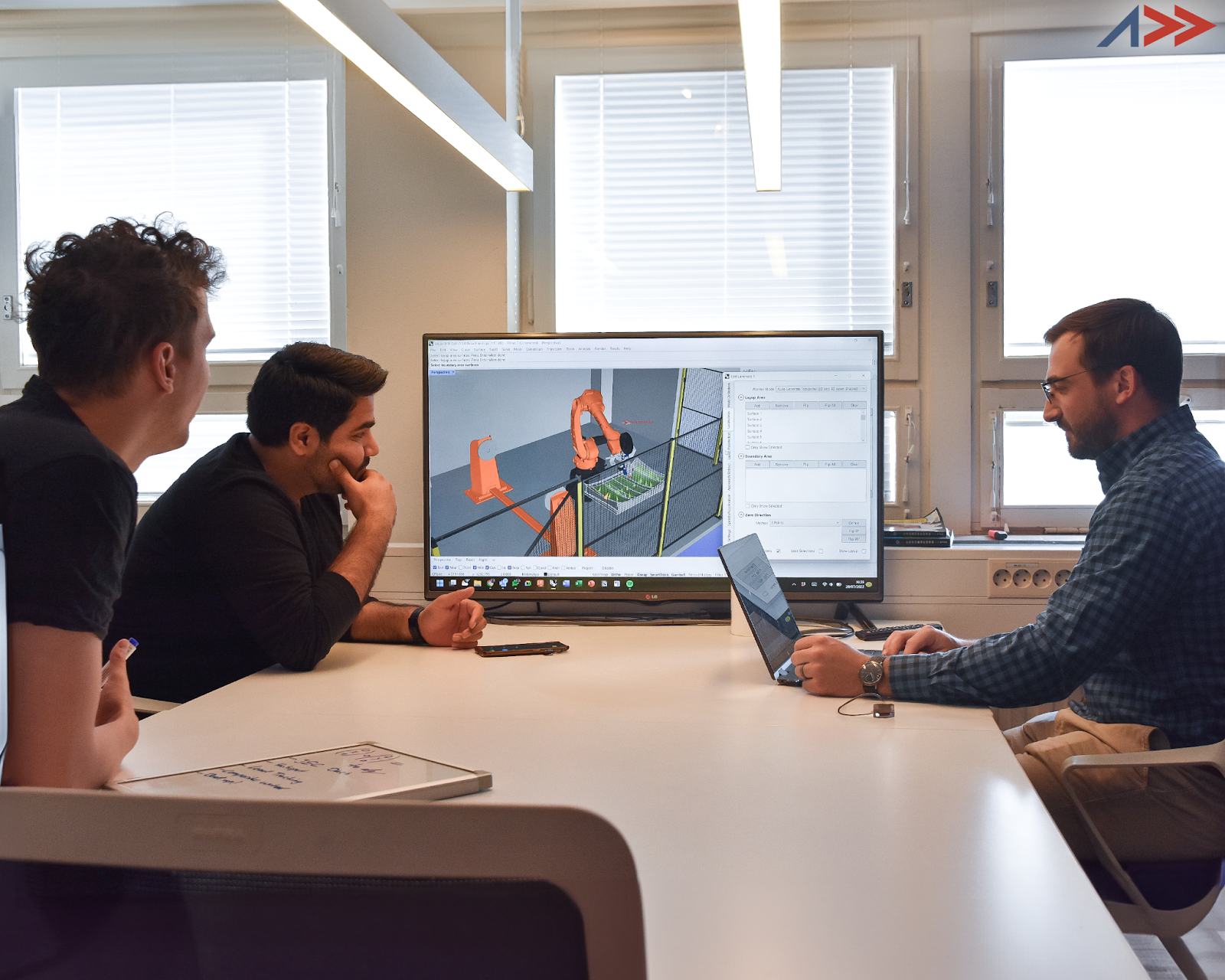
AFP cell simulation in AddPath — reach, clearance, and wrist torque validated before a purchase order is raised.
Simulate Before You Buy
An offline simulation against your actual part geometry is the most valuable step available before committing to a robot purchase.
Before entering a robot selection conversation, a well-prepared buyer has:
Buyers who arrive without this list aren't less capable — they're just earlier in the process. Robot selection before process definition produces guesses, not decisions.
Learn More
Addcomposites builds AFP systems designed to work on standard industrial robots — no custom hardware required. If you're at the robot selection stage, the applications team has worked through this decision across aerospace, automotive, and industrial composites customers. Contact us to get a recommendation specific to your part and process.
Contact Us for a ConsultationReferences
- Addcomposites Sales & Applications Team Interview — Addcomposites Sales & Applications (March 2026). Primary source for field insights on buyer behavior, robot selection patterns, and real-world failure modes in AFP installations.
- Addcomposites Technical Specifications — AFP-XS, AFP-X, and AddX product documentation. Payload ranges, TCP offset specifications, and system weight data.
- ISO 9283:1998 — Industrial robots – Procedure for the presentation of specifications – Accuracy and repeatability. International standard defining the distinction between repeatability and absolute accuracy in robotic systems.
- KUKA KR Quantec Series Specifications — Technical datasheet and controller documentation. Reference for external axis synchronization, continuous path interpolation, and motion control flexibility.
- ABB IRB 6700 and IRB 14000 Series — Robot specifications and controller capabilities. Comparative reference for path accuracy and motion control configurations.
- FANUC M-20iD/35 and M-710iC/70 Series — Specifications and collaborative robot motion control. Industry reference for standard robot classes used in AFP applications.
- Lukaszewicz, G., et al. (2012). "Automated Fiber Placement — Mechanical Properties." Composites Part A: Applied Science and Manufacturing, 43(10). Peer-reviewed validation of process parameters and accuracy tolerances in AFP manufacturing.
- Croft, E., Wierczynski, G., & Benhabib, B. (2011). "Optimal Force and Torque Estimation in Compliant Manipulation Tasks." IEEE Transactions on Robotics and Automation. Technical reference for understanding wrist torque in continuous path processes.
- Boisse, P., et al. (2015). Composite Reinforcements for Optimum Performance (2nd Edition). Woodhead Publishing. Comprehensive reference on composite manufacturing processes, including fiber tension and compaction forces in automated layup.
- Addcomposites Internal Deployment Database (2024–2026) — Field data from 50+ customer installations across aerospace, automotive, and industrial composites. Source for robot brand prevalence, failure pattern analysis, and cost breakdown observations.