The Laminate That Stores Energy: How Tailored Stitching Is Making Structural Batteries AFP-Ready
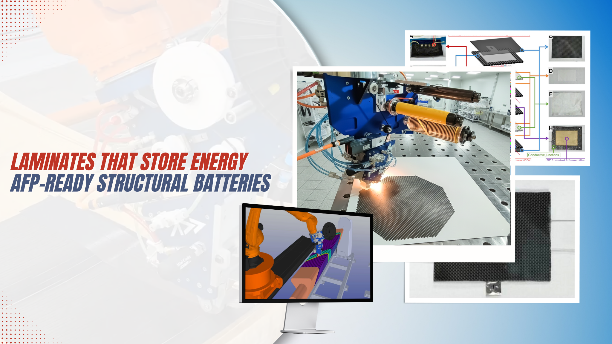
A 2026 paper in Advanced Science demonstrates that the manufacturing gap between structural battery concept and production-scale composite processing is narrower than the industry assumed — and the solution runs through thermoplastic resin systems your AFP machine already knows how to handle.
For the better part of a decade, the structural battery has occupied a frustrating position in advanced composite design: theoretically transformative, practically elusive. The idea — that a carbon-fiber laminate could simultaneously carry mechanical load and store electrochemical energy, eliminating the parasitic mass of a separate battery pack — is compelling enough to attract sustained investment from aerospace, automotive, and defence programmes worldwide. The execution, however, has been persistently undermined by a set of interrelated manufacturing problems that no single materials innovation has been able to resolve all at once.
A paper published in Advanced Science (Wiley) in late 2025 by Park, Kim, Kwon, Lee, and colleagues from Chosun University, KAIST, and Kyungpook National University changes that calculus in a meaningful way. Their work — Tailored Stitching and Vertical Stacking for High-Voltage Multifunctional Structural Batteries with Enhanced Electrochemical-Mechanical Coupling — is not primarily a materials paper. It is a manufacturing architecture paper. And for anyone building composite structures with automated fibre placement, the implications are direct.
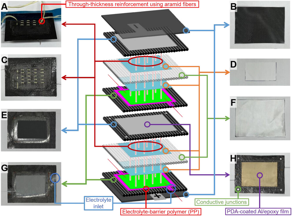
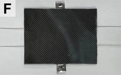
Architecture of the stitched high-voltage structural battery laminate: (A) through-thickness aramid stitching, (B) outer CFRP face sheet, (C) stitch pattern, (D) PP/PE/PP separator, (E) LTO electrode on CFRP current collector, (F) glass-fabric interleaf, (G) LFP electrode on CFRP current collector, (H) CFRP/Al conductive junctions for series coupling.
The Problem Stack
To appreciate what this paper solves, it helps to understand why structural batteries have been so difficult to manufacture at scale. The challenge is not any single failure mode — it is a cascade of them that are geometrically linked.
The Structural Battery Manufacturing Problem Cascade
Prior work has addressed individual items in this stack. Ionic liquid electrolytes improve environmental stability but reduce ionic conductivity. Rigid composite face skins suppress delamination but add mass. Post-injection electrolyte filling (injecting liquid electrolyte after high-temperature cure) decouples thermal processing from electrochemical degradation — but only works if the laminate architecture provides a reliable sealed channel for the fluid to travel through.
Park et al. address all four challenges simultaneously through a combination of three architectural innovations: selective thermoplastic encapsulation using polypropylene (PP) and Elium resin, through-thickness aramid fibre stitching at controlled densities, and vertical cell stacking for series-connected high-voltage operation.
The Architecture: What Is Actually Being Built
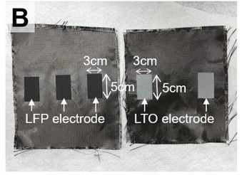
The structural battery described in the paper is a CFRP laminate in which plain-weave carbon fibre fabric functions simultaneously as the mechanical reinforcement and the current collector for both electrodes. LiFePO₄ (LFP) cathode and Li₄Ti₅O₁₂ (LTO) anode slurries are doctor-blade coated onto separate carbon fabric layers within a masked 3 cm × 5 cm electrode zone, then vacuum-dried. The result is an electrode/CFRP current collector — a single ply that is both structural and electrochemically active.
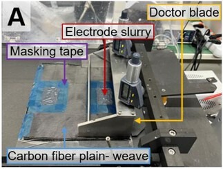
Doctor-blade-assisted slurry coating on masked carbon fibre fabric — the 3 cm × 5 cm electrode zone is defined by Teflon tape before casting.
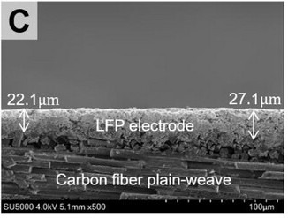
Cross-sectional SEM of the electrode-coated CFRP current collector, confirming uniform coating thickness of 22–28 μm on the carbon fibre plain-weave substrate.
The cell stack, from bottom to top, reads as follows:
Single-Cell Layer Stack
|
CFRP Face Sheet
Elium matrix
|
|
|
Al Barrier Film
6 μm, PDA-coated
|
|
|
LFP Electrode
Carbon fabric / Elium prepreg
22–28 μm active coating PP border 5 mm wide |
|
|
PP/PE/PP Separator
16 μm trilayer
|
|
|
Glass Fibre Plain-Weave
Electrical isolator
|
|
|
PP/PE/PP Separator
16 μm trilayer
|
|
|
LTO Electrode
Carbon fabric / Elium prepreg
22–28 μm active coating PP border + optical tube inlet |
|
|
Al Barrier Film
6 μm, PDA-coated
|
|
|
CFRP Face Sheet
Elium matrix
|
The Elium resin — a polymethyl methacrylate (PMMA)-based thermoplastic — is applied in liquid form before polymerisation, which allows it to be selectively masked away from the electrode regions using Teflon tape. PP films are then bonded around the electrode perimeter using a soldering iron, creating a hermetic thermoplastic border that provides the low oxygen and moisture permeability that Elium alone cannot offer. The paper reports that PP is the dominant encapsulant specifically because, unlike epoxy, it resists both O₂ and water vapour at levels sufficient to protect lithium-ion electrolytes — a property well established in food packaging literature and confirmed here for battery applications.
Hot-press consolidation profile: 140 °C and 14 bar sustained for 30 minutes to unify the laminate structure and activate the Elium matrix.
Post-Consolidation Electrolyte Injection
Electrolyte is injected after full high-temperature consolidation (140 °C, 14 bar, 30 minutes) via an embedded optical tube channel — a PMMA tube with inner diameter 0.38 mm from which a fluoropolymer-coated steel wire is withdrawn post-cure, leaving a clean PP-lined injection pathway. Vacuum-assisted infusion draws the liquid electrolyte through the stack from within a glove box, and the channel is sealed with a PVDF wire and epoxy cap.
The Stitching Variable: Why Density Is the Critical Parameter
The architectural innovation that distinguishes this work from previous CFRP structural batteries is the systematic application of through-thickness aramid stitching across the active electrode zone — and the careful characterisation of what happens as stitch density changes.
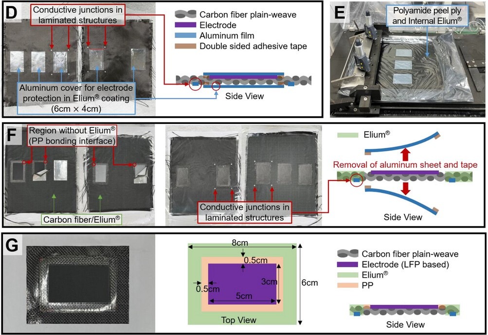
Stitching process and density configurations: (D) side view of Kevlar KM2 thread being introduced through the laminate; top views of stitched structural batteries at (E) 5.0 mm, (F) 3.33 mm, and (G) 2.5 mm stitch spacing.
Four configurations were tested: unstitched, loosely stitched (5 mm spacing), moderately stitched (3.33 mm spacing), and densely stitched (2.5 mm spacing). The Kevlar KM2 yarn was tensioned during stitching to minimise slack and ensure local ply compaction. The key finding is that performance is not monotonic with density: there is an optimum, and it sits at moderate density.
Stitch Density vs Dual-Function Performance
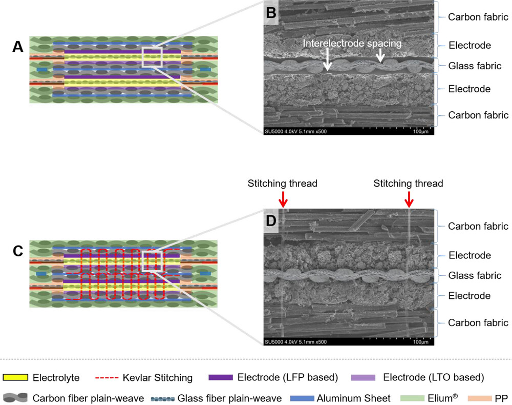
Cross-sectional SEM of unstitched (B) and moderately stitched (D) structural battery laminates. In the stitched configuration, aramid threads (arrows) compact the electrode–separator stack to near-contact, minimising ionic path length.
The mechanism behind the optimum is well-characterised in the paper and consistent with the stitched composite literature. At moderate density, the aramid threads compact the ply stack locally, reducing electrode-to-electrode spacing to near the separator filament diameter — creating a geometry with only micrometre-scale, electrolyte-filled residual voids between electrodes. This minimises ionic path length, reduces both solution resistance (R_s) and charge-transfer resistance (R_ct) at the electrode-electrolyte interface, and produces the highest energy density (42.2 Wh kg⁻¹ against total structural mass — a 14% improvement over the unstitched baseline).
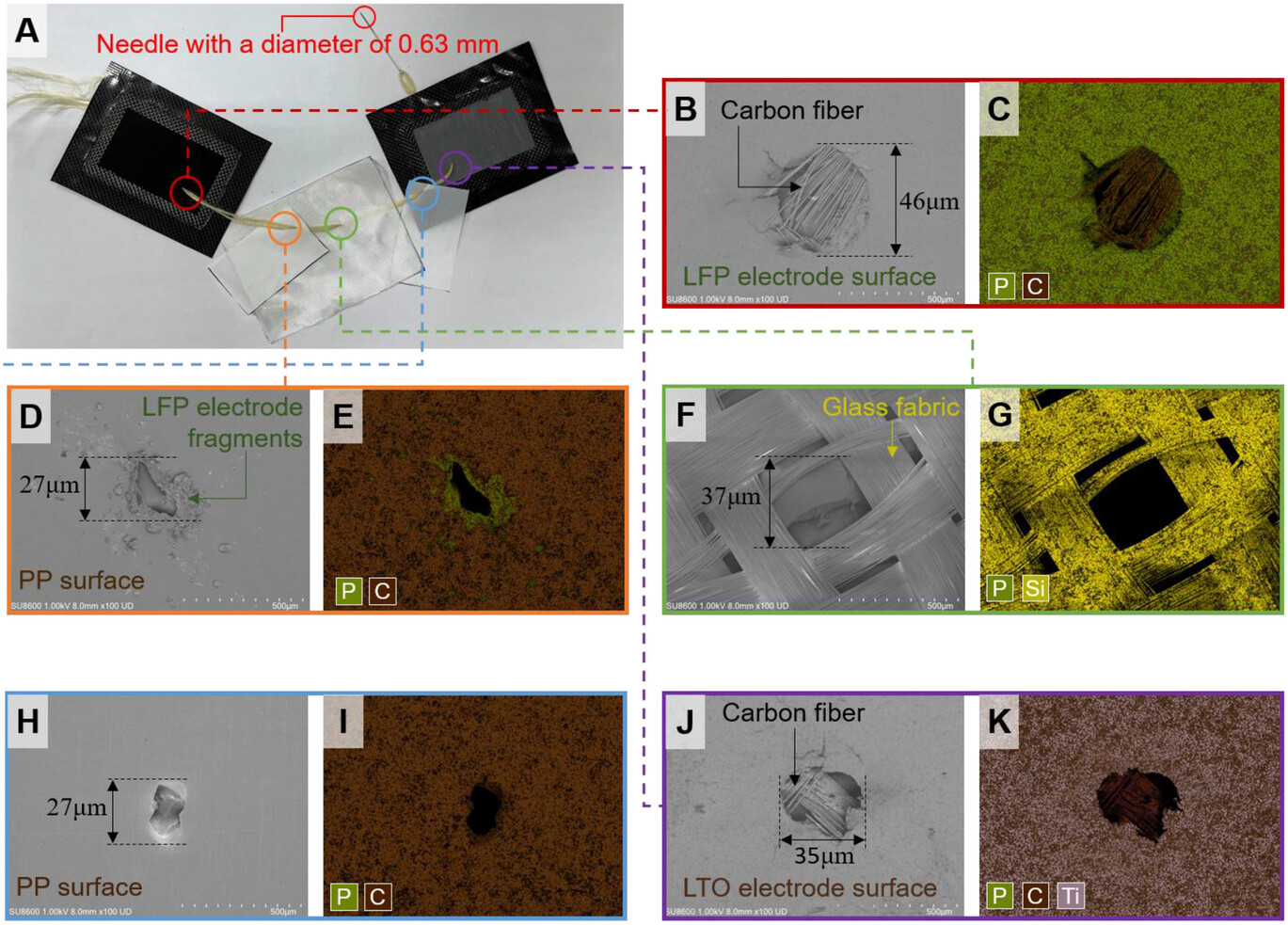
SEM and EDS analysis of stitch-penetrated layers: (B/C) LFP electrode surface showing ~46 μm damage zone and phosphorus loss; (D/E) PP/PE/PP separator showing captured LFP fragments; (F/G) glass fabric layer showing no phosphorus propagation beyond the first separator.
At dense stitching, needle penetrations begin to locally damage the electrode coating, exposing bare carbon fibre and reducing the active surface area. SEM and EDS analysis in the paper confirms that LFP fragments are displaced at each penetration site and migrate into the first PP/PE/PP separator layer. The critical safety finding is that the trilayer PP/PE/PP membrane acts as an effective mechanical filter: fragments do not propagate past the first separator into the glass fibre interlayer or the opposing electrode. Electrical testing across multiple densely-stitched specimens confirmed no shorting events when the PP/PE/PP layer was present on both sides of the glass fabric.
The Vertical Stacking Solution for High Voltage
Most published structural battery work stops at a single cell operating at 1.7–1.9 V. This is fine for demonstrating the concept, but electric vehicles and high-performance UAVs (DJI Matrice 350 RTK operating at >40 V, cited in the paper) require multi-cell series integration. Conventional CFRP structural battery designs achieve this through side-by-side planar layouts, which introduce inter-cell dead space, long interconnect runs, and structural discontinuities at cell boundaries.
The paper proposes and demonstrates vertical stacking — laminating cells in series along the thickness direction — as the solution.
Planar vs Vertical Cell Stacking
Final configuration of the vertically stacked high-voltage structural battery: two cells laminated in series along the thickness direction with PDA-coated aluminium barrier films and CFRP/Elium protective skins.
PDA Surface Treatment: A Critical Manufacturing Detail
The dopamine (PDA) surface treatment applied to the 6 μm aluminium barrier films between cells shifts the failure mode toward cohesive fracture within the PDA/adhesive interphase, producing a 40.7% increase in flexural strength (215.6 MPa) and 41.3% increase in stiffness (14.7 GPa). This is among the strongest flexural performance reported for a CFRP structural battery using a liquid electrolyte, competitive with recent results from Chen et al. (181 MPa), Han et al. (203 MPa), and Liu et al. (201 MPa) in the same class of system.
Under Load: Electrochemical Stability During Bending
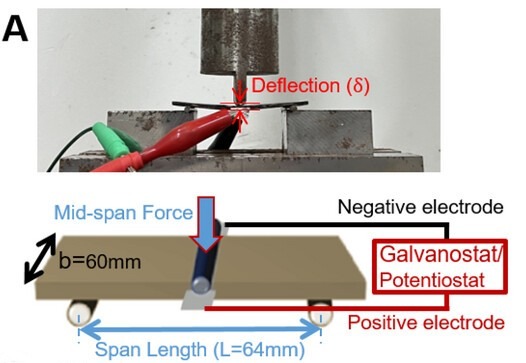
In situ three-point bending and charge–discharge test setup: controlled deflection (δ) is applied at mid-span while the structural battery is simultaneously cycled galvanostatically.
Simultaneous Mechanical and Electrochemical Testing
The coupled mechanical-electrochemical test — charging and discharging the battery while simultaneously applying controlled deflection in a three-point bending fixture — is where the stitching advantage becomes most visible in practical terms.
Capacity Retention Under Progressive Bending Deflection

Inter-electrode deformation under bending: (A) unstitched — bending induces significant electrode separation and electrolyte starvation; (B) loosely stitched — moderate restraint; (C) densely stitched — electrode displacement is effectively suppressed.
The physical mechanism is illustrated by Figure 11 in the paper: without stitching, bending-induced delamination opens electrode gaps that electrolyte cannot bridge, starving ion transport. Stitching threads act as localised mechanical tethers that resist interlaminar separation, maintaining electrode proximity and electrolyte wetting across the active region even as the laminate flexes. At large deflections the denser stitch pattern's greater tether density becomes the dominant factor. Critically, after full load removal, stitched cells recover to approximately 85% of their original capacity — versus 81–82% for the unstitched control — confirming that the stitching limits irreversible interfacial damage, not merely deformation.
The AFP Angle: Why This Is a Manufacturing Paper in Disguise
Here is the manufacturing-critical read on this paper that the abstract does not foreground. Every process step described is compatible with, or directly enabled by, thermoplastic AFP manufacturing:

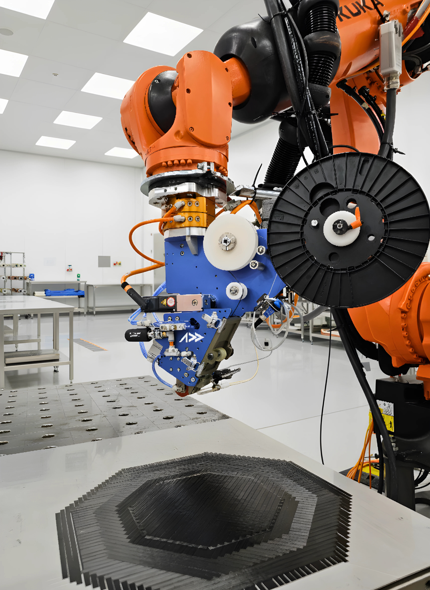
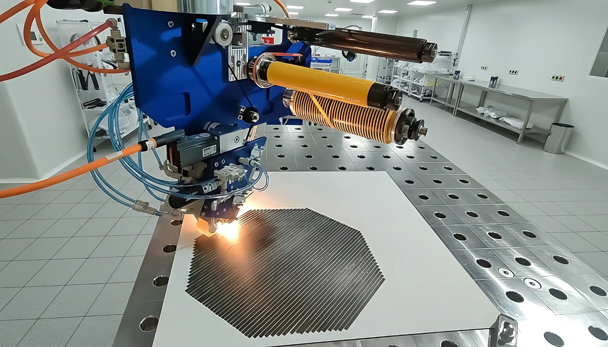
AFP-XS laser heating zone during thermoplastic tape consolidation — the processing regime that makes Elium-based structural battery laminates manufacturable on existing AFP equipment.
Elium as the Matrix
Elium 150 is applied in liquid form before polymerisation — precisely the resin handling regime that makes it attractive for AFP thermoplastic prepreg manufacture. Unlike thermoset epoxy, Elium can be re-consolidated under heat and pressure, supports the 140 °C / 14-bar hot-press cycle used here, and offers the selective masking and resin-boundary control that distinguishes this architecture. AFP systems that handle thermoplastic prepreg tapes — including Addcomposites' AFP-X — are designed around the resin flow and consolidation dynamics that make selective Elium deposition possible at the ply level.
AFP-XS ply-by-ply deposition — programmed fibre path precision that manual layup cannot replicate.
Ply-by-Ply Functional Zoning
The architecture requires precise placement of: CFRP/Elium plies in structural zones, PP-bounded electrode plies in active zones, aluminium barrier films at interlaminar boundaries, and glass fibre interlayers for electrical isolation. This is exactly the kind of heterogeneous ply stack that AFP's programmable fibre path and material-switching capability is designed to handle. Manual layup of this architecture is time-consuming and positionally inconsistent; AFP-based layup closes both problems.
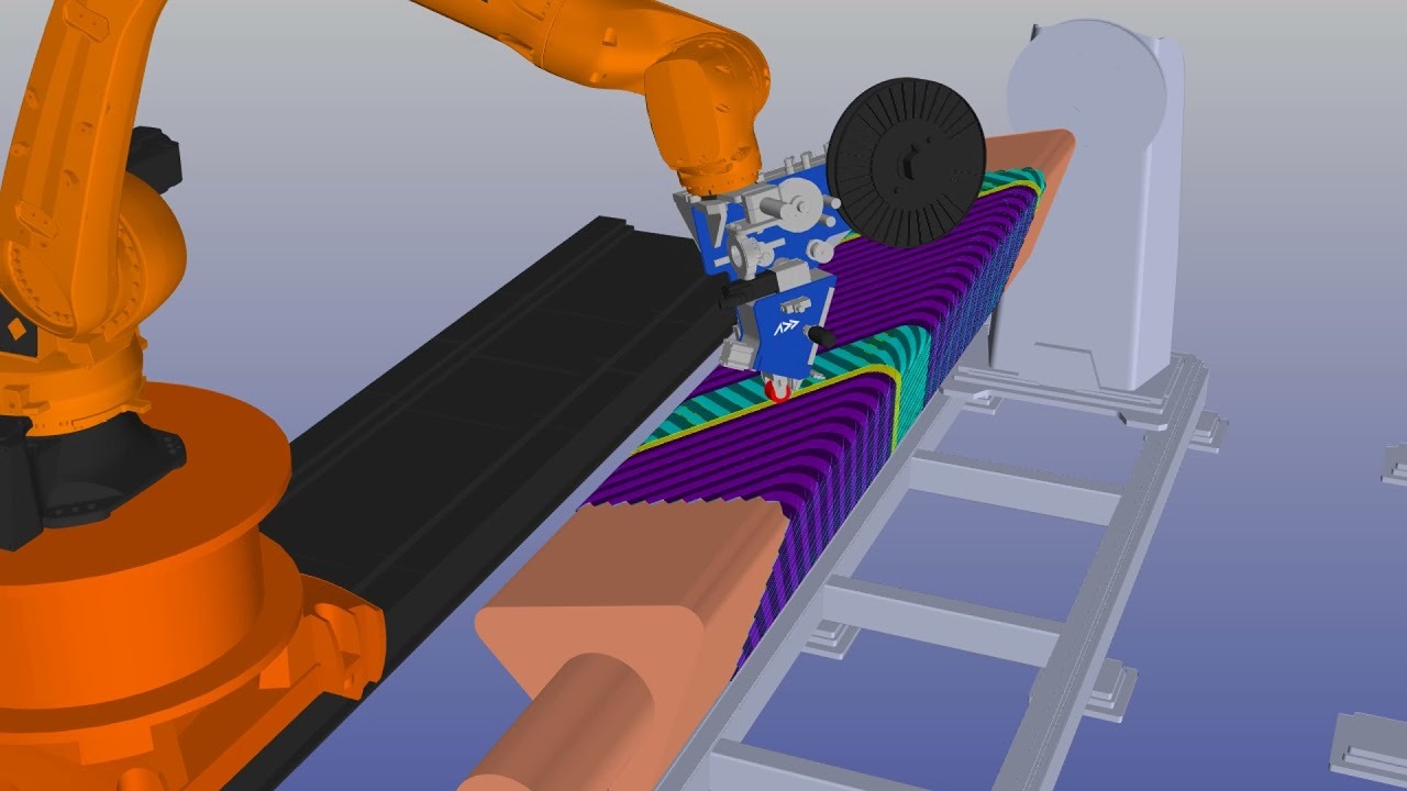
AFP-XS ply sequence simulation — each layer deposited to a programmed orientation, eliminating the positional variability that makes stitch-penetration geometry unpredictable in hand-laid alternatives.
Scalability of the Stitching Step
The authors note that continuous fibre reinforcement simplifies manufacture of large-area structural batteries. Stitching, as a post-layup operation, scales linearly with area — but the quality of the substrate it stitches through determines whether the needle path is repeatable. AFP-laid laminates offer dimensional consistency and controlled ply consolidation that makes the stitch-penetration geometry more predictable than hand-laid alternatives, reducing the risk of electrode damage variability that the paper identifies as the primary mechanism of dense-stitching performance loss.
The Post-Injection Electrolyte Pathway
The optical tube injection channel is embedded during layup — a feature that AFP can reproduce as a deliberate local inclusion, analogous to the embedded sensor and insert capabilities that AFP-X users already deploy for SHM and fastener integration. The sealing sequence (PVDF wire + epoxy cap) is a bench operation that does not require any modification to the AFP process itself.
For AFP-XS users operating in the UAV and small satellite structural component space — precisely the applications the paper cites as the primary demand drivers — this means the enabling manufacturing technology for structural battery integration is not a future development. It is available today, and the process architecture has now been validated at the cell level.
Where the Numbers Sit
The paper's reported multifunctional efficiency (MFE) for the PDA-modified moderately stitched system is 0.551, calculated against a standard LFP cell baseline of 90 Wh kg⁻¹ and a unidirectional CFRP modulus baseline of 128 GPa. The authors position this within the 0.16–0.58 range typical of carbon-fibre-based multifunctional materials, noting that most published systems optimise one function at the expense of the other.
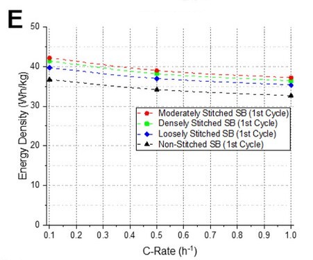
Energy density at 0.1C across stitching configurations: moderate stitching (3.33 mm spacing) achieves peak performance at 42.2 Wh kg⁻¹ referenced to total structural mass.
Energy Density in Context
The energy density of 42.2 Wh kg⁻¹ is achieved using standard carbon fibre electrodes with liquid electrolyte — no solid-state electrolyte, no exotic chemistry. Systems using solid electrolytes outperform it on individual metrics, but those systems face their own manufacturing integration challenges: solid electrolyte coverage at scale, limited interlaminar bonding options, and process temperature constraints that solid-state chemistry imposes.
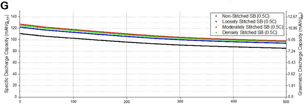
Long-term cycling performance at 0.5C over 500 cycles: the moderately stitched structural battery retains 77% of initial capacity, with all stitched configurations outperforming the unstitched baseline throughout.
The Right Comparison Baseline
The liquid-electrolyte architecture described here sacrifices peak energy density in exchange for process compatibility with AFP manufacturing and demonstrated stability over 500 cycles (77% capacity retention at 0.5C).
For the aerospace and UAV structural designer, the relevant comparison is not against a standalone LFP pouch cell. It is against a CFRP structure plus a separate battery pack. At 42.2 Wh kg⁻¹ referenced to total structural mass — including the CFRP current collectors, glass fibre interlayer, aluminium barriers, and Elium matrix — the structural battery is doing electrochemical work with mass that was always going to be in the structure. That is the core value proposition, and it now has a validated manufacturing path.
What Comes Next
The authors explicitly identify the modular nature of their enhancement strategy. The stitching architecture, the vertical stacking configuration, the thermoplastic encapsulation approach, and the dopamine surface treatment are described as complementary rather than mutually exclusive. Future combinations with damage-tolerant electrode formulations, stitch-compatible gel or soft polymer electrolytes, and automated stitching heads — already in development for preform manufacturing — are natural extensions.
For the AFP community, the near-term development question is whether Elium-based CFRP prepreg tape with embedded PP electrode zones can be produced in a format compatible with slit-tape AFP heads. The selective masking and doctor-blade coating steps described in the paper translate reasonably directly to a modified tape manufacturing process, where the electrode slurry is deposited onto the fibre substrate before resin infiltration in designated tape segments. The dimensional tolerances involved — 3 cm × 5 cm electrode zones within an 8 cm × 6 cm laminate ply — are comfortably within AFP placement accuracy.
The structural battery is moving from curiosity to component. The manufacturing architecture to get it there is already in the room.
Learn More
Interested in how AFP-XS or AFP-X can be configured for thermoplastic structural battery laminate research? Get in touch with the Addcomposites team.
Contact Us for a ConsultationReferences
- Park, G., Kim, C.-G., Kwon, H., Lee, J. D., Park, J., Son, Y., Kim, J. G., & Cha, J.-H. (2026). Tailored Stitching and Vertical Stacking for High-Voltage Multifunctional Structural Batteries with Enhanced Electrochemical–Mechanical Coupling. Advanced Science, 13, e14967. https://doi.org/10.1002/advs.202514967. Open access under Creative Commons Attribution License.
- Addcomposites. AFP-XS Automated Fiber Placement System. https://www.addcomposites.com/afp-xs
This post was prepared by the Addcomposites team. Addcomposites develops the AFP-XS automated fiber placement platform. For questions about thermoplastic AFP process development, contact us at addcomposites.com.
