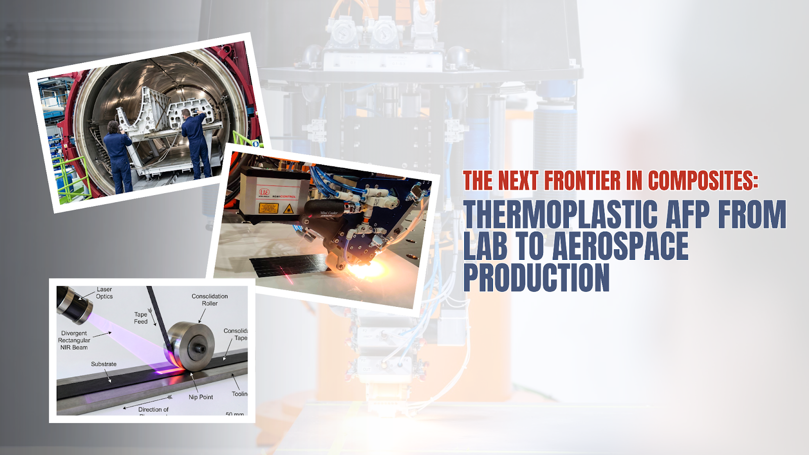
Thermoplastic AFP: The Next Frontier in Composite Manufacturing
Thermoplastic AFP is moving from research labs to production floors. Here's what it actually is, why the industry is shifting, and what it takes to run it — with a clear-eyed look at what's solved and what isn't yet.
Why Thermosets Built the Industry — and Why That's Changing
Thermoset composites built the aerospace industry. Carbon fibre reinforced epoxy is what the A320 is made of, what the 787 is made of, what makes modern aircraft structures 20–30% lighter than aluminium equivalents. For fifty years, the combination of thermoset resin and autoclave processing has been the gold standard for structural composite manufacturing.
.png)
But a technology reaching maturity is also a technology approaching its ceiling.
Autoclave processing is expensive, capital-intensive, and a hard constraint on production rate. Thermoset parts cannot be welded, reformed, or recycled without significant energy input and material loss. The skills required to lay up thermoset prepreg are expensive and increasingly scarce. And as sustainability regulations tighten, the end-of-life fate of thermoset composites — largely landfill or incineration — is becoming a procurement issue, not just an environmental one.
Thermoplastic composites change the equation on all of these dimensions. And thermoplastic Automated Fiber Placement (AFP) is the manufacturing process that makes them viable for complex structural geometries at production rates aerospace programs actually need.
This is not a future technology. The physics works. The properties are demonstrated. The question now is execution — process robustness, supply chain depth, and accessible hardware that makes thermoplastic AFP available below the tier-1 contractor level.
This post covers what thermoplastic AFP is, why it matters, what the engineering challenges actually are, and where the technology is heading.
The Material Science: What Makes Thermoplastics Different
At the material level, the difference between thermosets and thermoplastics is a single thermodynamic property. Thermosets cure through an irreversible chemical cross-linking reaction. Once the polymer network forms, it doesn't unmake. Thermoplastics, by contrast, soften above their glass transition or melting temperature and re-solidify on cooling. That phase transition is repeatable — and it is the foundation for everything that makes thermoplastic composites interesting.
End of life: landfill / incineration.
End of life: pelletise + reuse.
This reversibility is not a minor footnote. It is what enables fastener-free assembly via welding, field repair without an autoclave, and end-of-life material recovery — three capabilities that thermosets categorically cannot provide.
Matrix Selection: The Thermal Processing Window
Not all thermoplastics are equal in AFP applications. The processing temperature — the temperature at which the matrix becomes workable — determines the hardware specification required, the energy input needed, and the thermal stresses induced in the laminate during processing.
AFP 220–260°C
AFP 250–290°C
AFP 320–360°C
AFP 340–380°C
AFP 360–420°C
AFP 370–420°C
AFP 350–420°C
Amorphous polymers (e.g. PEI) soften above Tg without a distinct melt point. All bars scaled to 420°C maximum.
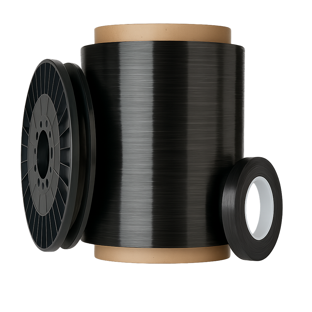
CF/PEEK unidirectional tape — no freezer, no expiry, no autoclave.
PEEK & PEKK
Dominate aerospace primary structure — combining mechanical properties (CAI, OHT, bearing strength) with the thermal stability needed for aerostructure service environments.
PPS & PEI
Widely used for secondary structure, brackets, clips, and interior panels where the processing temperature is more forgiving and the structural demands are lower.
PA-Family
Driving automotive adoption — where cycle time and cost pressure mean PEEK-grade properties are rarely justified, but fibre-reinforced thermoplastics still deliver significant structural benefit.
In-Situ Consolidation: Where the Engineering Complexity Lives
The defining capability of thermoplastic AFP — and the source of most of its engineering challenge — is in-situ consolidation (ISC). In conventional thermoset AFP, you lay up the laminate and then autoclave it separately. In thermoplastic AFP with ISC, you melt the matrix, press it, and consolidate it in a single pass as the head traverses the layup surface. No secondary oven. No autoclave. One step.
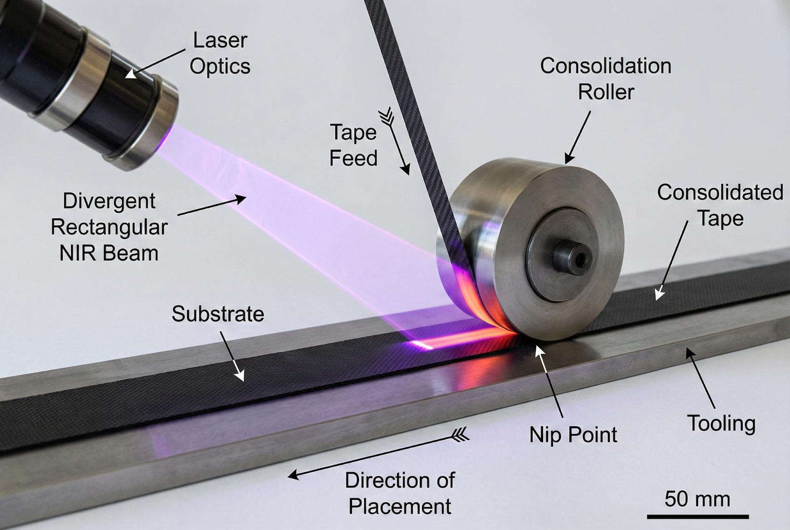
Laser in-situ consolidation at the nip point — tape fed, heated above Tm in milliseconds, and compacted in a single pass.
Heats tape + substrate above Tm
in milliseconds
Drives out voids, ensures contact
Transfers heat to substrate
Target: semi-crystalline morphology
The Coupling Problem
These four variables are coupled. Changing layup speed changes dwell time and therefore heat input, which changes the required laser power, which changes the temperature gradient, which changes the cooling rate, which changes crystallinity. On a complex geometry with varying surface angles, the coupling changes continuously along the tow path.
This is why the process software is not a secondary concern in thermoplastic AFP — it is central to the process. The thermal model that predicts nip-point temperature as a function of speed, geometry, ambient temperature, and prior ply state needs to be embedded in the trajectory generator, not bolted on after the fact.
Heat Source Comparison: Laser, Hot Gas, and Ultrasonic
The choice of heat source is one of the most consequential decisions in thermoplastic AFP system design. Three technologies dominate:
- Precise energy delivery
- Fast response time
- Narrow heat-affected zone
- Enables high layup speeds
- Highly repeatable
- High equipment cost
- CF absorbs >90% — fibre overheating risk
- Requires safety interlocks
- Line-of-sight only
- Lower equipment cost
- Good for complex geometries
- Mature, established technology
- Low safety overhead
- Wider heat-affected zone
- Slower thermal response
- Less energy-efficient
- Convective → diffuse heating
- Less suitable for high speed
- Localised heating
- No line-of-sight constraint
- Suitable for semi-crystalline TP
- Enables welding applications
- Limited to semi-crystalline materials
- Complex head mechanics
- Not yet at production TRL for AFP
Laser AFP is the dominant choice for PEEK and PEKK primary structure applications. The precision of energy delivery matters when the processing window is narrow — PEEK needs to be above ~343°C to consolidate and below ~430°C to avoid degradation, a window of roughly 85°C at the nip point. Laser diodes hit that window repeatably at layup speeds of 100–300 mm/s.
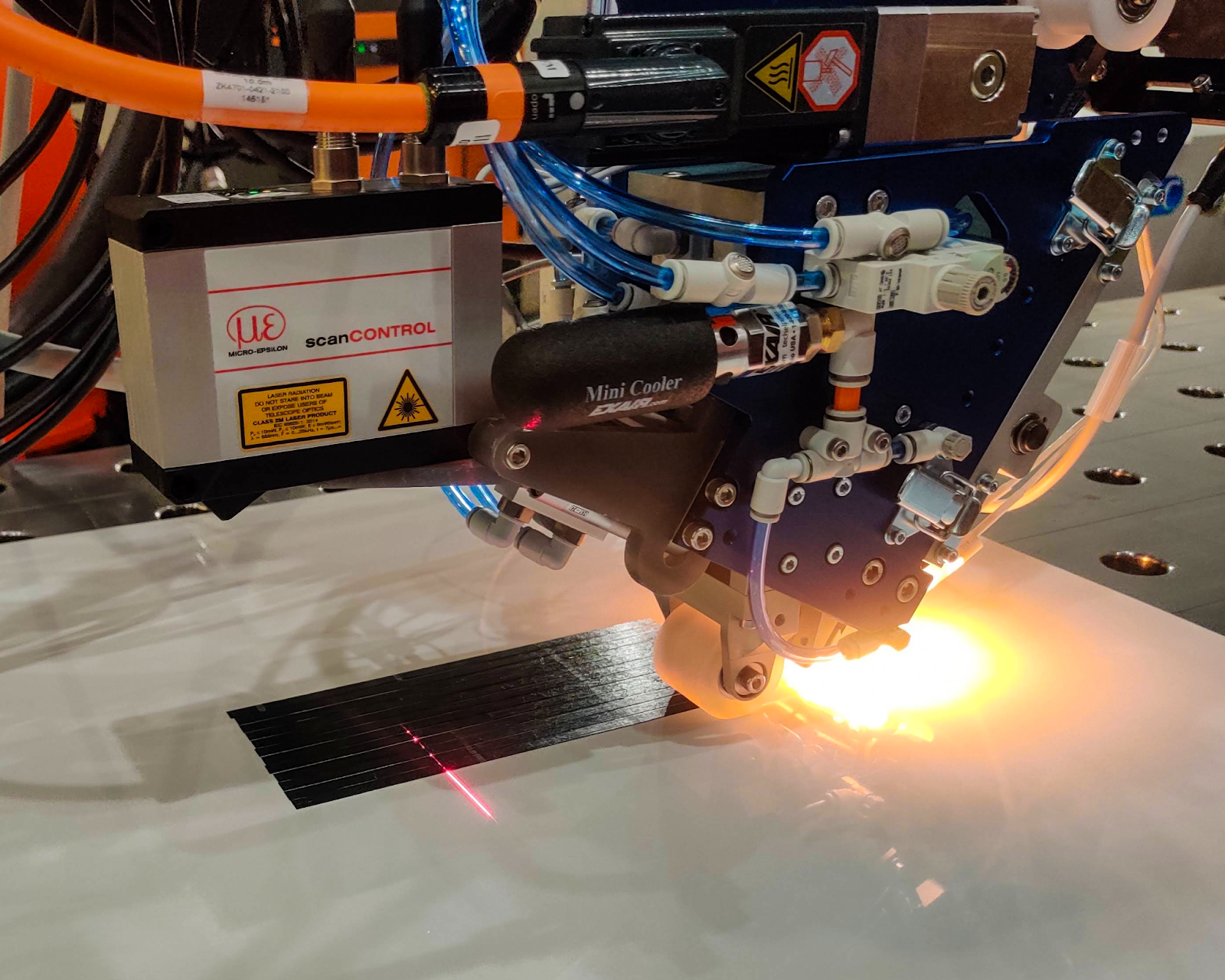
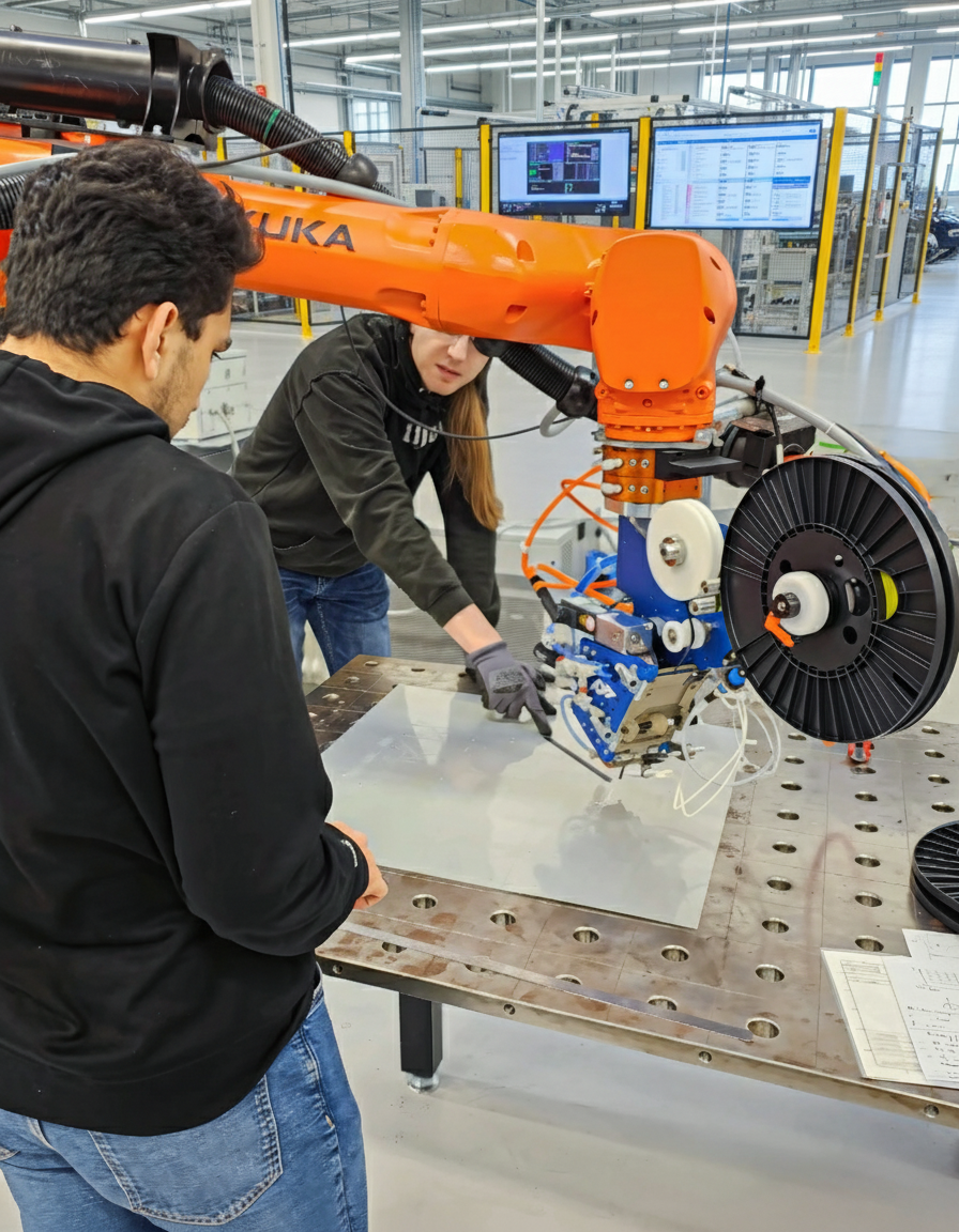
AFP-XS on a KUKA arm — laser heating at the nip point, in-process inspection running, thermoplastic tows consolidating in a single pass
Hot gas is widely used in lower-temperature applications (PPS, PEI) and in facilities where the capital cost of a laser system is not justified. DLR's research programmes have demonstrated excellent ISC results with hot gas at moderate layup speeds.
The AFP Head: Mechanical Design Requirements at 400°C
Running an AFP head at thermoplastic temperatures puts demands on the mechanical design that don't exist in thermoset systems. A thermoset AFP head operates at ambient temperature — it's a precision tape dispenser. A thermoplastic AFP head is operating at temperatures that exceed the service limit of most standard engineering plastics, many bearing materials, and some aluminium alloys.
- Tape guide + steering mechanism
- Receives tape at 20°C ambient from spool
- Delivers tape to nip point at ~400°C
- Thermal gradient management — insulation between feed path and heat zone
- Laser optics or hot gas nozzle
- High-temp materials: ceramics, Inconel
- Precisely positioned relative to nip point
- Water-cooled housing to protect robot wrist
- Material: PTFE, silicon carbide, or high-temp metal alloy
- Spring-loaded or servo-controlled actuation
- Force feedback for closed-loop process control
- Must maintain consistent contact on curved geometry
This thermal management challenge is why thermoplastic AFP heads are not trivially adapted from thermoset heads. The engineering of the thermal boundary between the robot interface (cool) and the processing zone (extremely hot) is a significant mechanical design problem in its own right.
Robot-Agnostic Design
Addcomposites' approach on the AFP-XS is to design the head as a self-contained thermal unit that mounts on any standard industrial robot flange without requiring robot modifications. The thermal isolation is managed within the head, not by the robot — which is what makes the system robot-agnostic and deployable on existing KUKA, Fanuc, ABB, and UR platforms.
Unique Capabilities: What Thermoplastic AFP Actually Unlocks
Beyond removing the autoclave from the process chain, thermoplastic composites enable manufacturing approaches that are structurally impossible with thermosets. These are not incremental improvements — they are qualitatively different capabilities.
1. Structural Welding: Fastener-Free Assembly
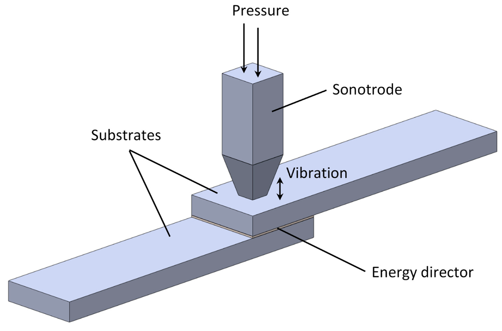
Ultrasonic Welding (USW) — Image credit: MDPI, from Advanced Thermoplastic Composite Welding for Aerospace Applications
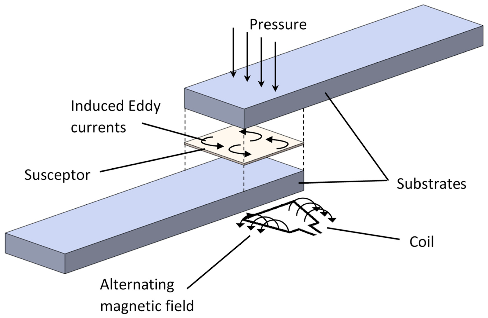
Induction Welding (IW) — Image credit: MDPI, from Advanced Thermoplastic Composite Welding for Aerospace Applications
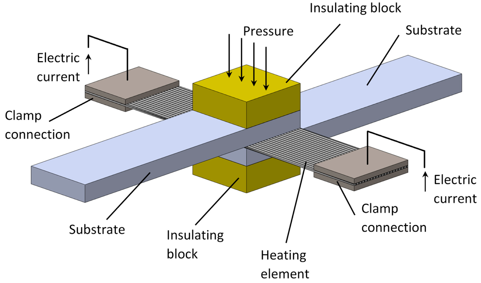
Resistance Welding (RW) — Image credit: MDPI, from Advanced Thermoplastic Composite Welding for Aerospace Applications
The welding capability is where thermoplastic composites generate the most commercial interest at the assembly level. A conventional composite aircraft structure is held together with thousands of titanium fasteners. Each fastener requires a drilled hole — a stress concentration in the laminate — plus the fastener weight, sealant, and installation labour.
Thermoplastic welding removes the fastener. The joint strength is carried by the material, not by the fastener bearing on the hole. For secondary structure (clips, brackets, floor attachment), the cycle time reduction and weight saving are compelling. For primary structure skin-stringer interfaces, the structural efficiency gain is significant enough that multiple major OEMs are qualifying welded thermoplastic assembly processes for their next-generation aircraft programmes.
2. Re-Forming: From Flat to Shape Without Separate Layup
above Tg
+ cool
The ability to lay up flat and re-form is particularly valuable in prototyping and low-volume production. Instead of programming complex layup trajectories over a curved mandrel, you lay up on a flat tool (simple, fast, accurate), then thermoform the blank to the target geometry. The process is well-understood from the thermoplastic sheet forming industry and does not require specialised AFP-specific expertise.
3. In-Situ Repair
For defence and space applications where field repair without depot-level equipment is a genuine operational requirement, thermoplastic's repairability is not a nice-to-have — it is a programme requirement. Several advanced UAV and space launch vehicle programmes are specifying thermoplastic composites explicitly for this reason.
4. End-of-Life Recyclability
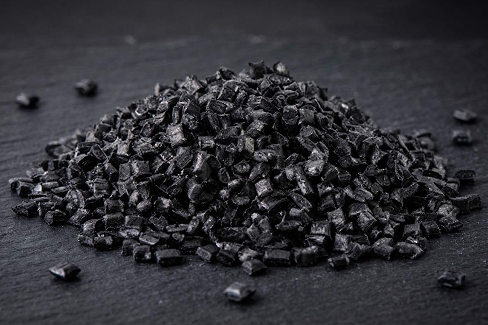
Chopped CFRTP recyclate — thermoplastic composite material recovered back into the supply chain as injection moulding feedstock.
The EU's End-of-Life Vehicle Directive (ELV) and evolving aircraft end-of-life regulations are forcing OEMs to quantify and report the recyclability of structural materials. For programmes where end-of-life recyclability is a contract requirement or a public-facing sustainability commitment, thermoplastic composites offer a documented pathway that thermosets simply do not.
The Challenges That Remain Real
The thermoplastic AFP story would be incomplete without an honest account of what is still being solved. Anyone telling you thermoplastic AFP is a mature, plug-and-play process is either selling something or working at a very different level of production than most manufacturers.
Void Content: Closing the Gap
Void content is the primary mechanical property differentiator between ISC-consolidated laminates and autoclave-consolidated laminates. Voids act as stress concentrations under compression loading. The gap has closed significantly over the past decade of research, and several programmes have demonstrated autoclave-equivalent properties with optimised ISC processes. But it requires careful process control — it does not happen automatically.
Crystallinity Management in PEEK and PEKK
Semi-crystalline thermoplastics develop their mechanical properties through the formation of crystalline regions in the polymer matrix during cooling. The degree of crystallinity — and crucially, its uniformity — depends on the cooling rate during processing.
PEKK's slower crystallisation kinetics give it a wider process window than PEEK, which is one reason several aerospace programmes have preferred PEKK despite its higher cost — it is more forgiving of process variation.
Material Cost Premium
The material cost premium is real and it does not fully disappear even at volume. But it is increasingly being evaluated in the context of whole-process economics — when you remove autoclave processing, reduce fastener count, and account for end-of-life material recovery, the lifetime cost per kilogram of finished structure often compares favourably.
Aerospace Applications: What Is Qualifying Now
The programmes in qualification today will set the standard process envelopes and material databases that the rest of the industry will inherit. Understanding where thermoplastic AFP is qualifying — and for what structural applications — tells you where the technology is genuinely headed.
The Airbus Wing of Tomorrow programme — the most significant composite primary structure development programme currently running — has demonstrated thermoplastic AFP stringer fabrication with induction welding for skin-stringer assembly. The weight and recurring cost targets for that programme cannot be met with thermoset processing. Thermoplastic AFP is not an option being evaluated; it is the enabling technology.
Fokker (now part of GKN Aerospace) has been producing thermoplastic control surfaces in series production for over a decade. The Gulfstream G500/G600 tail structures use thermoplastic composites. These are not research programmes — they are production programmes running today.
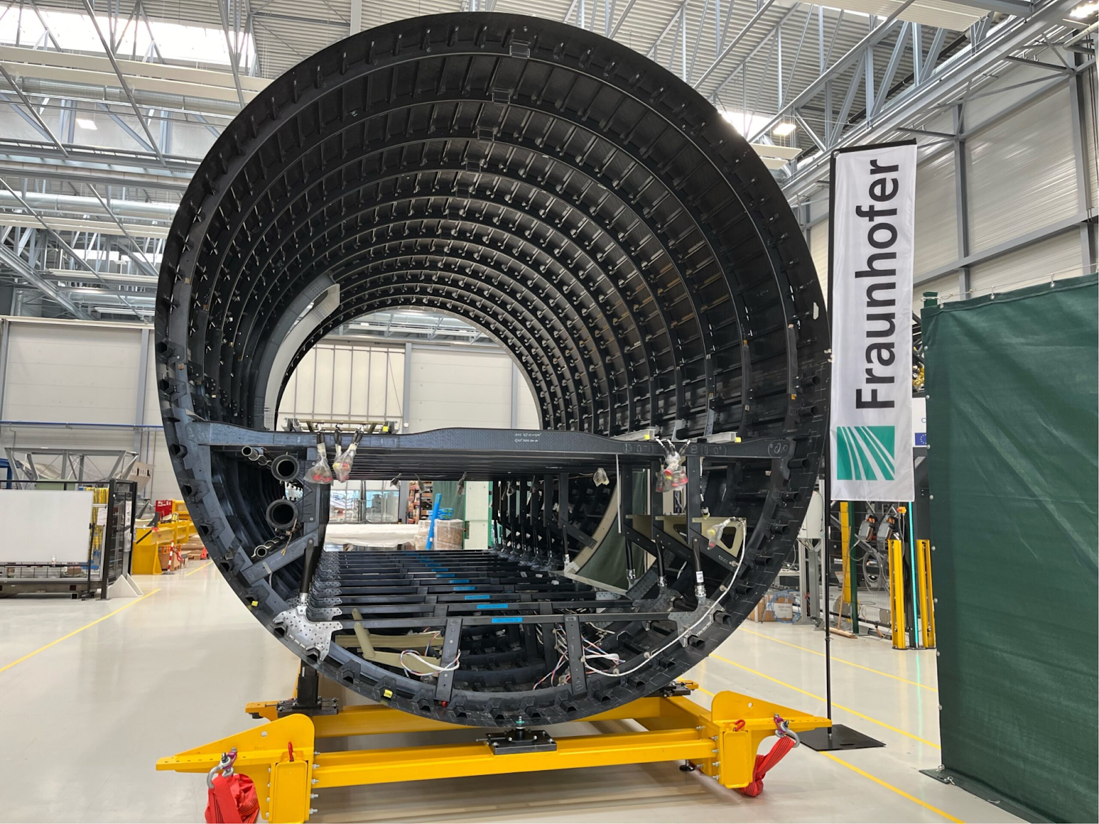
Image credit: Composites United, from New Architecture for Automated Production of the World's Largest Thermoplastic Aircraft Fuselage Demonstrated on a 1:1 Scale
The Process Chain: What It Takes to Run Thermoplastic AFP
If you are evaluating thermoplastic AFP for your facility, the full process chain looks like this:
The Most Underestimated Step
The step that is most often underestimated by teams new to thermoplastic AFP is step [3] — specifically the coupling between the CAM software and the thermal model. Thermoset AFP CAM software generates a valid programme if the geometry is correct and the steering radius is within limits. Thermoplastic AFP CAM software needs to additionally ensure that the thermal input at every point of every tow path is within the process window for that material, at that layup speed, on that surface angle, in that ply sequence.
That requirement is what makes software-first AFP development — designing the process parameters into the software from the beginning, not patching them in — the right architecture for thermoplastic AFP.
The Hardware Accessibility Shift
Historically, thermoplastic AFP required custom-built machines from a small number of specialist manufacturers. The machines were expensive, required specialist integration, and were effectively only accessible to tier-1 aerospace contractors and national research institutes.
That landscape has changed significantly in the past five years.
This shift matters because the qualification burden in aerospace is front-loaded at the prime level. By the time thermoplastic AFP processes are qualified for primary structure programmes at Airbus and Boeing, the material databases, process windows, and design allowables will be published and available to the supply chain. Tier-2 and tier-3 suppliers who have built their thermoplastic AFP process capability now will be positioned to execute those programmes when qualification transfers down the chain.
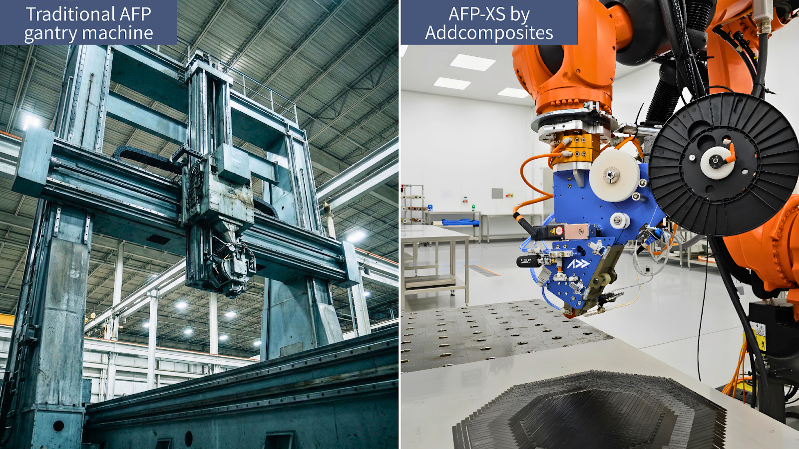
Traditional AFP gantry vs. AFP-XS by Addcomposites — the accessibility shift that brought thermoplastic AFP within reach of Tier 2/3 manufacturers and research institutes.
Where the Technology Is Heading: 2025–2035
The adoption curve for thermoplastic AFP is following a pattern composites manufacturing has seen before — aerospace primary qualification happens first, then the knowledge base and supply chain mature enough to enable industrial and defence adoption, then cost normalisation opens automotive and high-volume applications.
Technology Milestones Most Likely to Accelerate the Curve
Materials
Tape quality consistency from tier-2 tape suppliers is improving. PEKK pricing is coming down as volume increases. PA-CF tape quality for automotive AFP is reaching the consistency needed for structural applications.
Process Automation
Closed-loop process control — where the AFP system adjusts laser power and speed in real-time based on in-situ temperature feedback — is transitioning from research to production. This removes the process engineer from the parameter-adjustment loop.
Software
Thermal modelling fidelity is improving. Process simulation tools that predict consolidation quality before the first ply is laid are becoming commercially available. This compresses process development time from months to weeks.
Assembly Qualification
Resistance and induction welding of thermoplastic composite structures is in active qualification at multiple primes. Once skin-stringer welded assembly qualifies for primary structure, the recurring cost and weight arguments for thermoplastic AFP become undeniable.
The Bottom Line
Thermoplastic AFP is not a future technology waiting to be invented. It is a current technology in the middle of its industrialisation phase.
The physics is understood. The material properties are demonstrated. The manufacturing economics — no autoclave, weldable assembly, end-of-life recyclability, field-repairable structures — are compelling at multiple levels of the aerospace and industrial supply chain.
The questions now are process robustness at production rate, supply chain depth for thermoplastic tapes at volume, and software sophistication for managing the thermal process in complex geometry. None of these are fundamental barriers — they are engineering problems with known solution paths.
The manufacturers who build their thermoplastic AFP process capability now — before the qualification documents are published and the supply chain demand surge arrives — are the ones who will be positioned to capture the programmes when they come.
What Addcomposites Offers for Thermoplastic AFP
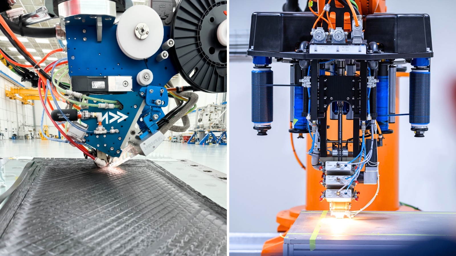
AFP-XS and AFP-X by Addcomposites — thermoplastic AFP from first demonstrator to full production rate, on any standard industrial robot.
The AFP-XS and AFP-X heads support thermoplastic processing up to 450°C, compatible with PEEK, PEKK, PAEK, PPS, and PEI tape on any standard industrial robot. AddPath, the open CAM software, includes thermal process modelling for thermoplastic trajectory generation.
AddPath: Software-First Thermoplastic AFP
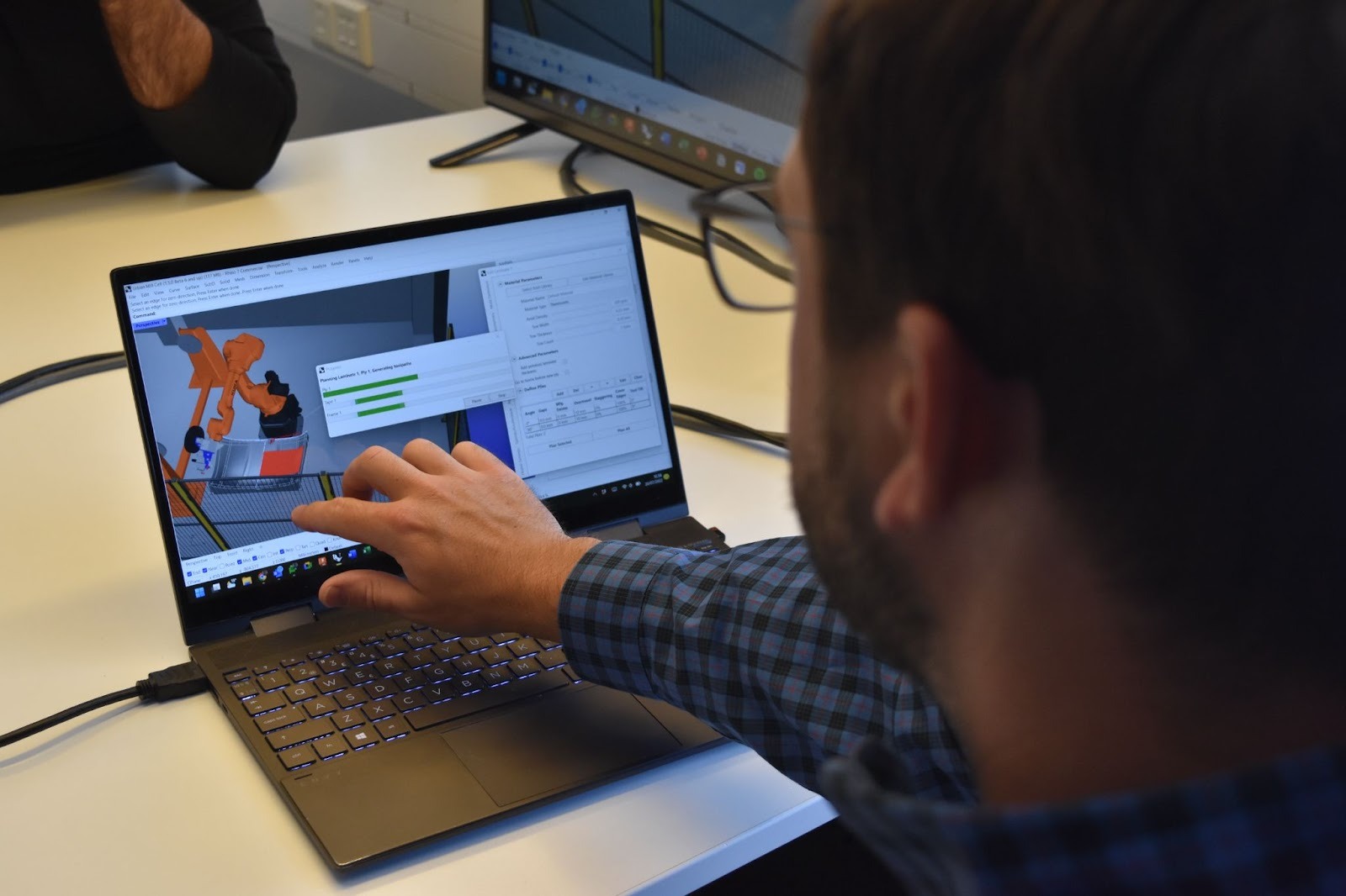
AddPath in action — trajectory generation and thermal process modelling running before the first tow is laid.
If you're evaluating thermoplastic AFP for your facility — whether that's a first demonstrator, a process development programme, or a production readiness exercise — we're happy to discuss your material, geometry, and throughput requirements.
Learn More
Get in touch to discuss your thermoplastic AFP application →
Contact Us for a ConsultationReferences
- Airbus / Clean Sky 2 — Thermoplastic Wing of Tomorrow Programme. Summary of the Clean Sky 2 Wing of Tomorrow initiative, covering thermoplastic composite stringer fabrication, induction welding for skin-stringer assembly, and large-scale demonstrator results at Airbus Broughton and partner facilities. https://www.cleansky.eu/wing-of-tomorrow
- DLR (German Aerospace Center) — Thermoplastic Composite Fuselage Research. DLR's Centre for Lightweight Production Technology (ZLP) thermoplastic AFP research, covering in-situ consolidation parameter optimisation, hot-gas torch AFP, and crystallinity management in PEEK and PEKK laminates. https://www.dlr.de/zlp
- NLR (Netherlands Aerospace Centre) — Thermoplastic Composite Manufacturing. NLR's published research on resistance welding of thermoplastic composites for aerospace primary structure, including ILSS, fatigue, and impact data for welded CF/PEEK joints. https://www.nlr.org/research/thermoplastic-composites
- CompositesWorld — "Thermoplastic Composites: Aerospace Applications and Market Trends" (2024). Market analysis and technology overview of thermoplastic AFP adoption across aerospace primary and secondary structure, covering major OEM programmes and supply chain development. https://www.compositesworld.com/articles/thermoplastic-composites-aerospace
- Victrex — PEEK and PAEK for AFP Applications: Processing Guide. Technical data and processing guidance for Victrex PEEK and PAEK UD tape in AFP applications, including recommended process windows, crystallinity development curves, and mechanical property benchmarks. https://www.victrex.com/composites/afp
- Solvay (now Syensqo) — APC-2 PEEK Unidirectional Tape Technical Data Sheet. Material specification for CF/PEEK APC-2 tape including Tg, Tm, melt viscosity, and AFP processing parameters. Industry reference data for PEEK in-situ consolidation process window. https://www.syensqo.com/composites
- Dávid Šmíd et al. — "In-Situ Consolidation of Thermoplastic Composites by AFP: Process Parameters and Mechanical Properties" (Composites Part A, 2022). Peer-reviewed study quantifying the relationship between AFP process parameters (speed, temperature, roller force) and void content in ISC-consolidated CF/PEEK laminates. https://doi.org/10.1016/j.compositesa.2022.107015
- Grouve, W.J.B. et al. — "Thermoplastic Composite Welding: A Review" (Composites Part B, 2023). Comprehensive review of resistance, induction, and ultrasonic welding of thermoplastic composites — joint strength data, process parameters, and qualification status for aerospace primary structure applications. https://doi.org/10.1016/j.compositesb.2023.110715
- MarketsandMarkets — Thermoplastic Composites Market Report 2024–2031. Market sizing (USD 14.3B by 2031), CAGR projections, and adoption segment analysis for thermoplastic composites with breakdown by resin type, fibre type, and end-use application. https://www.marketsandmarkets.com/Market-Reports/thermoplastic-composites-market-194.html
- JEC Composites — "Thermoplastic AFP: From Lab to Production" (JEC World 2025 Conference Proceedings). Conference proceedings from JEC World 2025 covering process maturity assessments, production-rate results from leading AFP thermoplastic programmes, and material supply chain development status. https://www.jeccomposites.com/jec-world
- Fokker Aerostructures / GKN Aerospace — Thermoplastic Composite Control Surfaces. Overview of Fokker's long-running thermoplastic composite production programmes for Gulfstream G500/G600 tail structures and Airbus A350 thermoplastic brackets — evidence of series production maturity. https://www.gknaerospace.com/thermoplastic-composites
- Addcomposites — AFP-XS Thermoplastic Processing Technical Documentation. Addcomposites technical documentation covering AFP-XS thermoplastic head specifications, supported material systems (PEEK, PEKK, PPS, PEI up to 450°C), robot compatibility, and AddPath thermal process modelling for thermoplastic trajectory generation. https://www.addcomposites.com/afp-xs
