Thermoplastic AFP: Why Your PEEK Parts Have Porosity — And How to Fix It
Published by Addcomposites | Technical Blog Series
Porosity is the silent killer of PEEK part quality. You've invested in the right material, the right machine, and the right process intent — and yet the ultrasonic C-scan comes back showing void content at 6, 8, even 10 percent. The aerospace customer rejects the coupon. The research paper loses its credibility. The production ramp stalls.
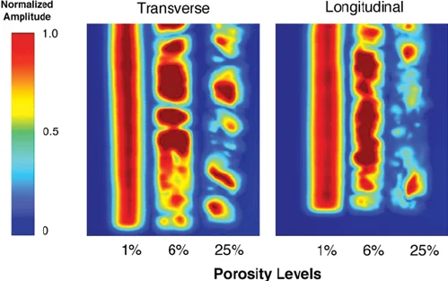
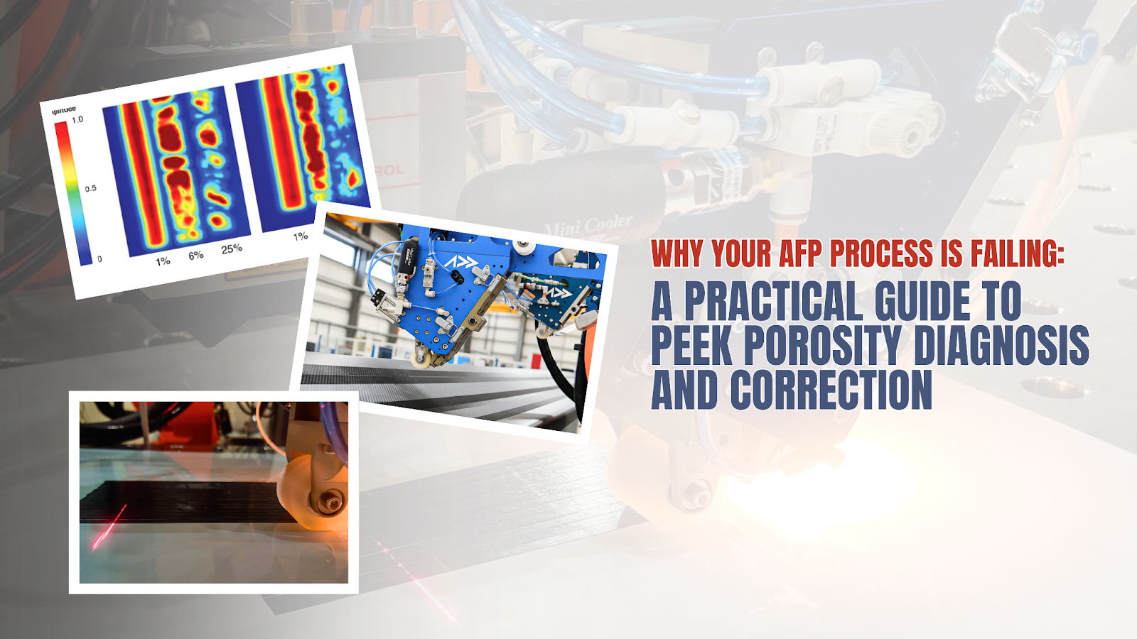
Ultrasonic C-scan amplitude maps showing void distribution in PEEK/CF laminates across increasing porosity levels. [Image: Awaja et al., ResearchGate – CC]
The frustrating reality is that PEEK porosity in Automated Fiber Placement (AFP) is almost never a materials problem. It's a process problem — and it's a solvable one, if you understand the four failure modes that together account for the vast majority of in-situ consolidation defects we see across customer programs.
This article breaks down each root cause with enough engineering depth to act on it, along with practical parameter windows, diagnostic approaches, and the visual patterns that tell you what went wrong before you even open a test report.
What "8% Porosity" Actually Means
Before diving into causes, it's worth grounding ourselves in what void content numbers mean mechanically. ASTM D2734 and the acid-digestion approach both give you a volumetric fraction of voids — but the distribution of those voids matters as much as the number.
At 8% void content, you're likely seeing both types. Interlaminar voids degrade interlaminar shear strength (ILSS) disproportionately — a 3% interlaminar void fraction can reduce ILSS by 20–30%. Intralaminar voids are more forgiving to in-plane tensile properties but become critical under fatigue loading and in compression.
The four root causes below each generate a characteristic void signature. Identifying which one dominates tells you where to fix the process.
Root Cause 1: Layup Speed Outrunning the Consolidation Window
This is the most common single cause of porosity in in-situ consolidated thermoplastic AFP, and it's counter-intuitive: the machine is doing exactly what you told it to do. The problem is that the process window for PEEK consolidation is narrow, and layup speed determines how much time the melt zone has to flow, wet the substrate, and consolidate before it cools past Tg.
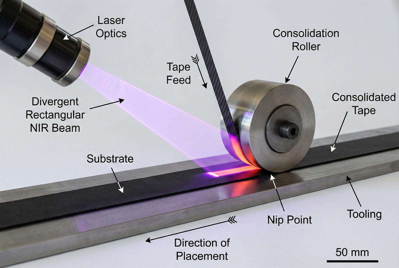
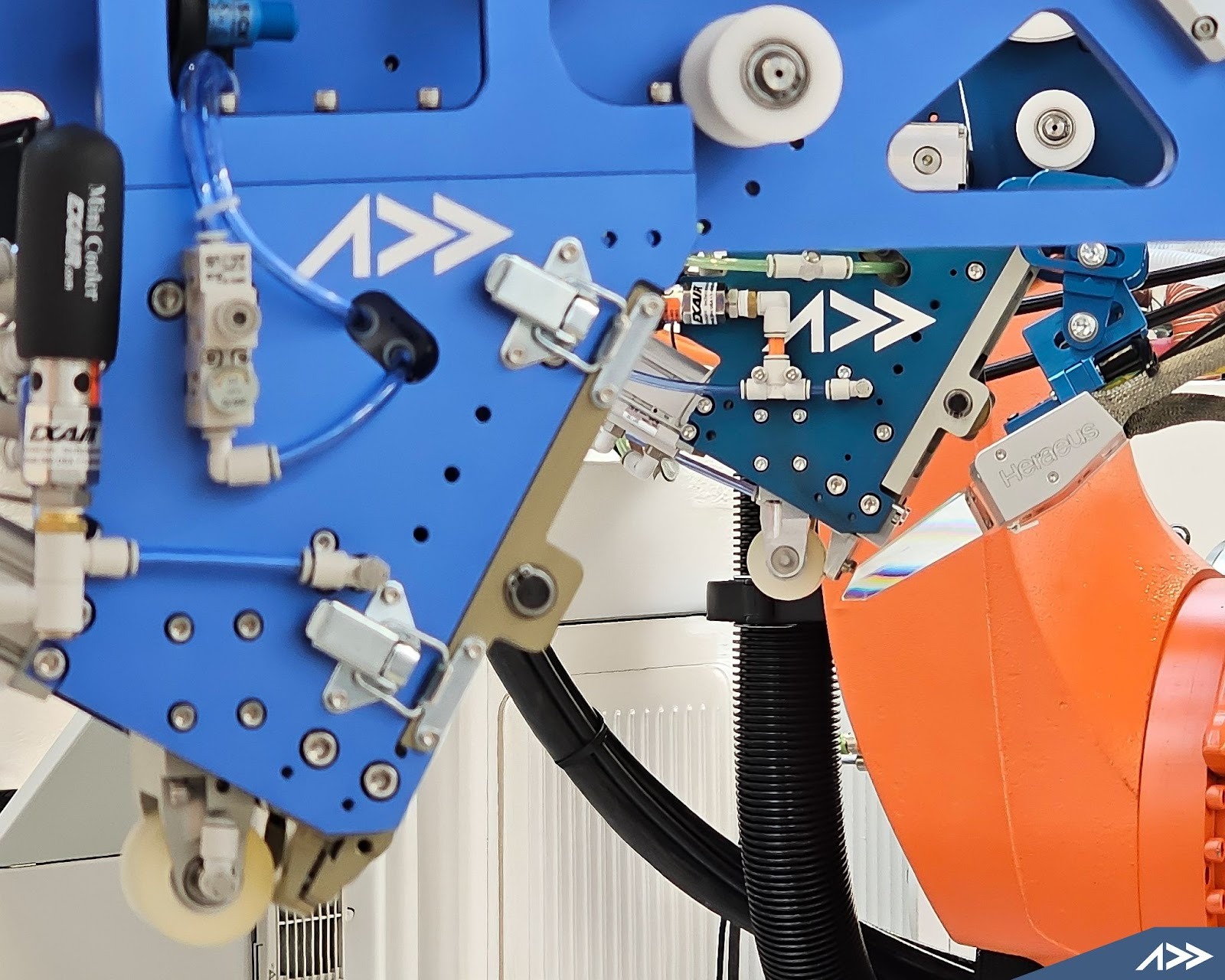
Laser AFP process showing the NIR heating zone, tape feed, nip point, and consolidation roller during in-situ thermoplastic tape placement.
The consolidation time budget
PEEK crystallises rapidly above ~200°C and sets its microstructure on the timescale of the nip point passage. At a layup speed of 300 mm/s with a typical laser spot or flash lamp footprint of ~25 mm in the layup direction, the melt residence time at the nip point is roughly 83 milliseconds.
The diagnostic signature: Porosity that increases linearly along the layup direction at corners or direction-change points, where the robot decelerates and accelerates. If your best void content is at the part edges and worst at the centre of long straight runs (where you're at full speed), speed is the primary driver.
What actually limits consolidation speed?
It's not just heat input — it's the coupled relationship between:
- Substrate temperature ahead of the nip — how hot is the previously laid ply when the new tape arrives? A cold substrate means the melt front has to cross a larger thermal gradient to bond.
- Melt viscosity of PEEK — PEEK at 380°C has a viscosity of approximately 400–800 Pa·s depending on molecular weight and shear rate. You need sufficient contact time for this melt to flow into the surface asperities of the substrate.
- Compaction pressure dwell time — the compaction roller applies pressure for the same duration as the melt zone. Halving the layup speed doubles both the thermal exposure and the compaction dwell time.
For PEEK in-situ consolidation, the practical limit for quality consolidation on flat laminates is 150–200 mm/s with most current heater configurations. Complex geometry, tight radii, and elevated stacking sequences push this down further.
Root Cause 2: Insufficient Compaction Pressure
Compaction pressure is the most frequently underestimated variable in thermoplastic AFP. In thermoset AFP, compaction is largely about tack and position accuracy — you're not trying to densify the laminate at the roller. In thermoplastic AFP, compaction at the nip point is the consolidation mechanism. The roller isn't just holding the tape in place; it's actively squeezing out voids while the resin is molten.
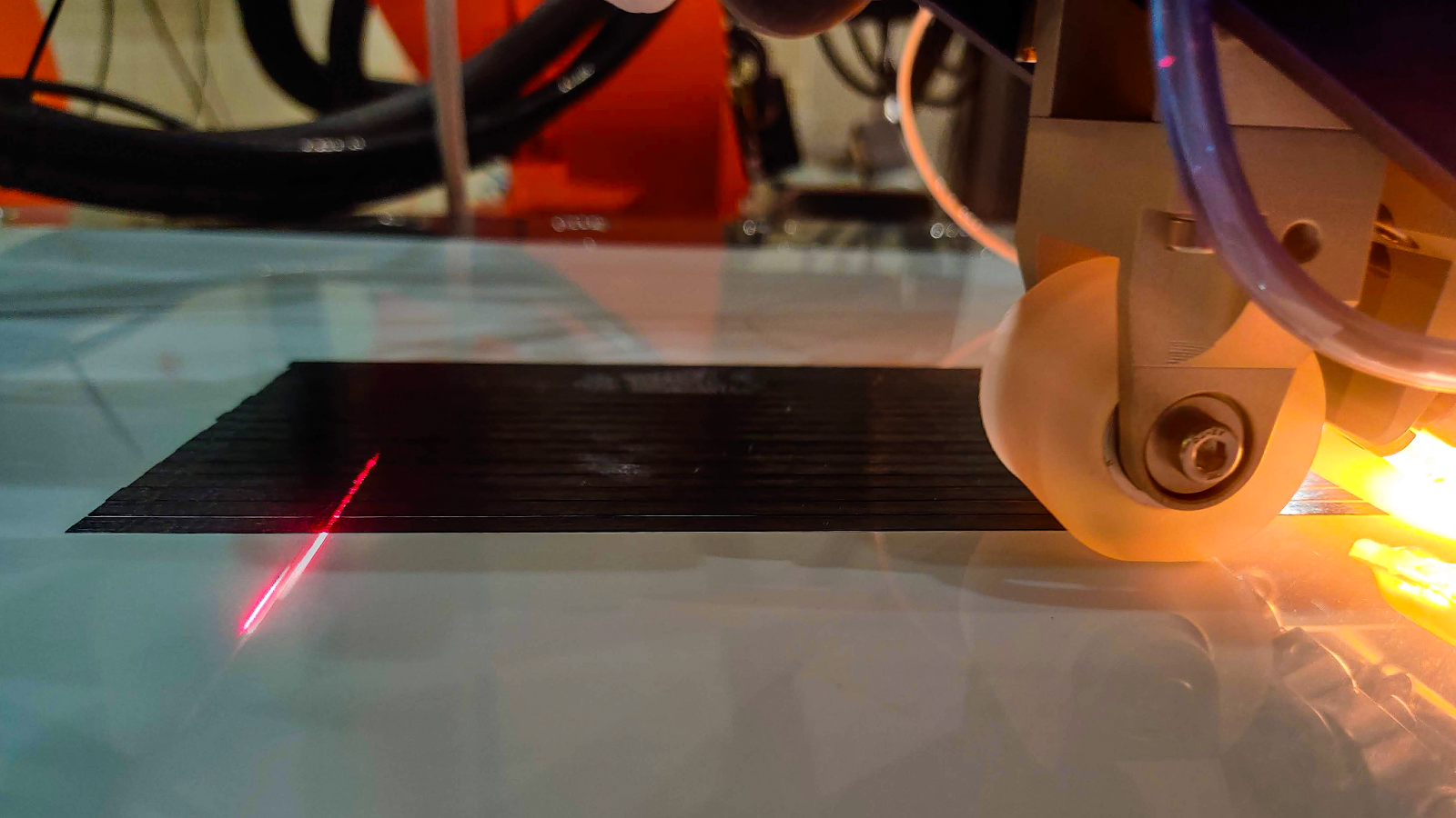
The compaction roller at the nip point during thermoplastic AFP — the only moment where pressure, heat, and time combine to squeeze out voids while the resin is still molten.
The pressure-void relationship
Most AFP systems allow the operator to set a force target (in Newtons) on the compaction roller actuator. What the operator rarely accounts for is that effective contact pressure is force divided by contact width — and contact width varies dramatically between roller types and surface geometries.
Beyond ~200 N/mm, gains diminish — roller compliance becomes the limiting factor
A 200 N force applied through a steel roller on a flat surface gives a contact width of perhaps 1–2 mm (Hertzian contact), delivering ~100–200 N/mm. The same 200 N through a compliant roller on a curved surface gives 5–8 mm contact width — 25–40 N/mm. Void content under these two conditions will differ by 3–5 percentage points even though the operator saw the same force setpoint.
Root Cause 3: Failure to Pre-Dry PEEK Tape
This one should be a solved problem in 2026. It isn't. We still regularly see customer samples with intralaminar void bands and a characteristic "Swiss cheese" cross-section that is the direct signature of moisture-driven void formation. PEEK tape absorbs moisture from ambient air, and that moisture becomes steam at processing temperatures — nucleating and growing voids that no amount of compaction pressure can squeeze out once they've formed.
The required pre-drying procedure
PEEK tape must be dried before every production run that follows an ambient exposure period. This is not optional, and it cannot be deferred:
Duration: 8–12 hours MINIMUM
16h for thick spools >250mm width
The diagnostic signature of moisture-driven porosity: Voids distributed uniformly across the ply thickness (not just at interfaces), with a round or slightly elongated morphology in the cross-section micrograph. The void content will be relatively uniform across the whole laminate (not concentrated at edges or direction-change points) because the moisture is distributed uniformly in the tape.
The fix is straightforward and cost-free. Pre-drying overnight before a production session is now standard practice in our customer base that has adopted it — and it has reduced average void content by 2–4 percentage points in every case.
Root Cause 4: Flash Lamp vs. Laser — It's Not Just an Energy Question
The fourth failure mode is the one that generates the most engineering debate: the choice of heating technology. Both flash lamp (broadband NIR) and laser (monochromatic, typically 940–980 nm diode) can achieve adequate melt temperatures for PEEK consolidation. But they behave very differently in the consolidation process, and misunderstanding these differences leads to parameter sets that look correct in the data sheet but produce unacceptable parts.

Flash lamp and laser heating configurations on the AFP-XS — two technologies, one consolidation objective.
Heat penetration depth and the recrystallisation problem
More uniform through-thickness — PEEK semi-transparent at 700–1400 nm
Steep gradient — CF carbon dominates absorption; higher surface temp needed for same through-thickness melt
Crystallinity and the recrystallisation race
Both heating technologies face the same fundamental problem: PEEK recrystallisation begins immediately as the temperature drops below ~390°C, and the crystallisation kinetics of PEEK are fast relative to the cooling rate in in-situ AFP. The result is that the recrystallisation pattern — and therefore the mechanical properties — are determined in the few hundred milliseconds between nip point and the point where the tape is below the cold crystallisation temperature.
→ Higher crystallinity variation → More residual stress → Potential void reopening at grain boundaries on cooldown
→ More uniform crystallinity → Better interlaminar properties
Practical parameter differences
For laser systems, AFP engineers typically need to:
- Run 20–40% higher surface temperature than the nominal PEEK melt temperature to ensure adequate through-thickness heating (accounting for the steep gradient)
- Use a larger beam footprint or raster pattern to extend the melt zone dwell time
- Consider a secondary pre-heating pass on the substrate ahead of the nip point on first-article runs
- Accept a narrower operating window at high layup speeds — the narrow gradient means the process is more sensitive to speed variation
For flash lamp systems:
- Manage spectral loading carefully — the broader wavelength output means more energy hitting the compaction roller and fixture, which can cause roller degradation and temperature drift over long runs
- Pulse frequency and duty cycle are the primary control levers; tuning these requires empirical characterisation per material batch
- Surface temperature measurement is more challenging with flash lamps because the pyrometer must be integrated for a different spectral band than the lamp output
Neither technology is inherently superior for PEEK consolidation quality. The best AFP programs have achieved sub-1% void content with both. What matters is matching the parameter set to the specific thermal behaviour of your heating technology — and not assuming that parameters developed for one technology will transfer directly to the other.
Diagnosing Your Specific Problem
If you're reading this because you're looking at an 8% void content number, here's the decision tree to identify the dominant root cause before adjusting parameters:
Putting It Together: A Parameter Baseline for PEEK in AFP
The table below provides starting-point parameters for PEEK/CF tape in AFP in-situ consolidation using a 6-axis robot system. These are empirically derived starting points — every material batch, tape width, and part geometry will require characterisation around these values.
| Parameter | Flash Lamp | Laser (940nm) |
|---|---|---|
| Layup speed (flat, 8-ply) | 100–150 mm/s | 100–150 mm/s |
| Layup speed (flat, >16-ply) | 80–120 mm/s | 80–100 mm/s |
| Surface temperature (tape) | 390–410°C | 410–430°C |
| Substrate temperature ahead | > 200°C | > 200°C |
| Compaction pressure | 120–180 N/mm | 100–160 N/mm |
| Compaction roller type | Silicone, 60–80° Shore A | PEEK or silicone |
| Tape pre-drying | 120°C, 12h min | 120°C, 12h min |
| Ambient RH during layup | < 40% | < 40% |
| Post-lay in-autoclave | Not required if void < 2% | Not required if void < 2% |
| Expected void content (flat, optimised) | < 1.5% | < 1.5% |
| Expected void content (first-article, untuned) | 3–6% | 4–8% |
Conclusion
Eight percent porosity in PEEK AFP parts is not a sign that in-situ consolidation doesn't work — it's a sign that one or more of four well-understood process variables is out of its operating window. In our experience across customer programs, the breakdown of dominant root causes looks roughly like this:
- ~40% of cases: Layup speed exceeds the consolidation time budget at the chosen power level
- ~30% of cases: Compaction pressure is set but not verified — effective contact pressure is too low
- ~20% of cases: Tape moisture — skipped or inadequate pre-drying
- ~10% of cases: Heating technology mismatch — laser parameters applied without accounting for the thermal gradient
The Bottom Line
None of these are hardware problems. They're process setup problems, and they're correctable without capital investment. The harder work is the empirical characterisation required to find the specific parameter window for your tape, your robot, and your geometry — but the baseline parameters and diagnostic framework above give you a structured path to get there.
If you're currently seeing elevated void content in your PEEK AFP program and want to work through the diagnosis systematically, our applications team is available for technical process reviews. We've seen this problem enough times across enough different system configurations that the path from 8% to sub-2% is rarely a surprise — it just requires methodical parameter work.
Addcomposites AFP systems support both flash lamp (Humm3 and compatible) and laser heater configurations. AddPath 2.0 includes process logging with per-ply speed, temperature, and force traces to support void content root cause analysis.
Contact us to get a recommendation specific to your part and process.
Learn More
Get in touch to discuss your thermoplastic AFP application →
Contact Us for a ConsultationReferences
- ASTM D2734-16, "Standard Test Methods for Void Content of Reinforced Plastics," ASTM International, West Conshohocken, PA, 2016.
- Grouve, W.J.B., "Crystallization and Consolidation of Thermoplastic Composites," Ph.D. dissertation, University of Twente, Enschede, Netherlands, 2012.
- Sonmez, F.O., and Akbulut, M., "Process Modeling of Thermoplastic Composite Tape Laying with On-Line Consolidation," Journal of Composite Materials, Vol. 41, No. 15, 2007, pp. 1793–1824.
- Khan, M.A., et al., "Numerical Simulation of In-situ Consolidation of Thermoplastic Composite AFP Process," Advanced Materials Research, Vols. 123-125, 2010, pp. 431–434.
