Thermoset CFRP Still Dominates But Thermoplastic Is Taking Ground Faster Than Most Manufacturers Realize
Based on: Wang et al., "Carbon Fiber Reinforced Thermoplastics: From Materials to Manufacturing and Applications," Advanced Materials, 2025. DOI: 10.1002/adma.202418709

Over the past five decades, carbon fiber reinforced polymers (CFRPs) rewrote what was possible in aerospace structures. Boeing's 787 Dreamliner reached 50 wt% CFRP. Airbus's A350 pushed to 53 wt%, realizing 50% lower structural maintenance costs over its predecessor. Light aircraft are now approaching 70–80 wt% CFRP. This first wave of adoption — aerospace-led, autoclave-cured, thermoset-dominated — is well understood.
What is less understood is that a second, more disruptive transition is already underway.
A landmark 2025 review published in Advanced Materials by Wang, Huo, Chevali, Hall, Offringa, Song, and Wang provides the most comprehensive current mapping of carbon fiber reinforced thermoplastics (CFRTs): where they stand today, where they outperform thermosets, and where the manufacturing gaps remain. For anyone making platform-level material system decisions — or building the automated fiber placement tools that serve those decisions — this paper is required reading.
This post draws directly from that review to build an honest picture of the thermoplastic transition, its constraints, and what it means for high-rate manufacturing strategy.
The Problem With Thermosets at Scale
Thermoset CFRPs dominate the current market, with epoxies leading. Their three-dimensional cross-linked networks deliver excellent mechanical properties, chemical resistance, and dimensional stability. But those same cross-links are the source of their most serious limitation: they cannot be melted, reformed, or welded.
At the end of service life, thermoset CFRP parts can only be landfilled or mechanically ground. Constructing "covalent adaptable networks" (CANs) within thermosets using dynamic covalent bonds — imine bonds, ester bonds, disulfide bonds — is an active research area, but as the review notes, CAN-based thermosets are still far from commercialization, with mechanical properties and stability remaining in question.
The second problem is production rate. Autoclave-cure thermosets require long cycle times, high capital infrastructure, and cannot be welded — meaning every joint in a structure requires mechanical fasteners. In a single fuselage section, this can mean thousands of titanium fastener installations, each adding weight, labor time, and a potential fatigue initiation site.
Material Systems · Process Comparison
Thermoset vs. Thermoplastic: Where They Diverge
Six dimensions that define the manufacturing and lifecycle gap
Thermoplastic CFRT — Performance vs. Metals
The review quantifies these differences directly: CFRTs replace metals with approximately 60% weight savings, five-fold increase in specific strength, two-fold increase in specific stiffness, and four-fold improvement in fatigue endurance. Out-of-autoclave processing alone changes the economics of large-structure manufacturing.
A Brief History of Why Thermoplastics Stalled — And Why They're Back
Thermoplastic composites were not a recent invention. The earliest work traces to the 1960s and 1970s, primarily in military and defense. DuPont, Phillips Petroleum, and Exxon all developed high-performance thermoplastics — PEEK was first patented in 1978. But through the 1990s, major chemical companies shifted focus back to thermoset composites. PEEK and its relatives were technically superior in many respects but commercially marginal.
CFRT History · Adoption Dynamics
CFRT Adoption: A Timeline of Stalls and Revivals
Eight decades from first patents to the thermoplastic renaissance
Two forces have changed that calculus in the current revival:
Net-Zero Mandates
The "audacious net zero goals" cited in the review are forcing aerospace and automotive OEMs to account for end-of-life recyclability in material system selection. CFRTs can be remelted, reformed, and recycled. Thermosets cannot.
Production Rate Pressure
Airbus and Boeing have publicly committed to production rates of 70–100 aircraft per month for single-aisle platforms. The Multifunctional Fuselage Demonstrator (MFFD) was designed explicitly to answer whether thermoplastic AFP plus welding could unlock those production rates.

The Polymer Landscape: Choosing Your Matrix
One of the clearest contributions of the Wang et al. review is its systematic treatment of the thermoplastic matrix options. The hierarchy runs from commodity plastics to ultra-high-performance polymers, with cost and processing temperature moving in the same direction.

Material Engineering · Selection Guide
Thermoplastic Matrix Selection: Performance vs. Processing Temperature
Hover any material node to explore specs and applications
LMPAEK deserves special attention. This "low-melt" poly(aryl ether ketone) offers much of PEEK's performance at a melting temperature 50–70°C lower. That difference is not cosmetic — it directly reduces infrastructure costs, energy consumption, and processing time. Cetex TC1225 and TC1320 (CF/LMPAEK tapes from Toray/TenCate) are processable in the 305–340°C window and have been validated in fuselage demonstrators. As the review notes, LMPAEK is often thought of as the fastest-manufacturing PAEK option — effective for automated fiber placement, stamp forming, and welding.
PPS is the cost-competitive workhorse. At $5–15/kg versus PEEK's $100–150/kg, PPS has found broad application across Airbus A330/A340 rudder nose ribs, aileron ribs, fixed-wing leading-edge assemblies, and Fokker 50/70/100 structural floor panels. Its brittleness is a real limitation, but for secondary structures it remains highly competitive.
PEI (Ultem) dominates aerospace interiors. Its 220°C glass transition, exceptional flame-smoke-toxicity properties, and large 100°C+ processing window make it the default for seat shells, ducting, galleys, and trolleys across Boeing 737/747/757/767 and Airbus A320 platforms.
| Matrix | Tm / Tg | Cost ($/kg) | Key Applications |
|---|---|---|---|
| PEEK | Tm: 343°C | $100–150 | Aerospace primary/secondary structures |
| PEKK | Tm: 305–360°C | >$200 | Aerospace primary structures |
| LMPAEK | Tm: 270–290°C | $150–200 | Fuselage demonstrators, AFP, stamp forming |
| PPS | Tm: 280–290°C | $5–15 | Airbus ribs, floor panels, secondary structures |
| PEI (Ultem) | Tg: ~220°C | $15–25 | Aerospace interiors, seat shells, ducting |
| PA6 / PA12 | Tm: 210–270°C | $2–5 | Automotive structures, pressure vessels |
| PP | Tm: 160–180°C | $2–5 | Automotive, orthopedic |
Fiber Forms: Continuous vs. Discontinuous
The choice of polymer matrix is only half the equation. The fiber architecture determines both mechanical performance and the viable processing routes.
Composite Materials · Architecture Guide
Carbon Fiber Architecture Map
Six fiber forms — from UD tape to nonwoven mat — mapped by structure, processability and performance
- Thickness: 0.13–0.25 mm
- FVF: 50–60 wt%
- AFP / ATL / TTW processable
- Best mechanical properties
- Fabric-based, fully impregnated
- ~60s cycle time
- Stamp forming + overmolding
- Automotive / industrial
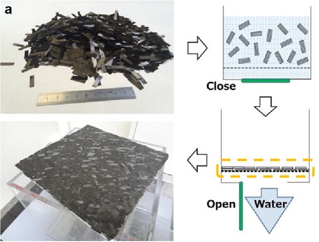
- From manufacturing offcuts
- Papermaking dispersal
- 10× faster resin impregnation
- Complex geometries at scale
- Pellet length: 3–4 mm
- Fiber in part: 0.2–0.4 mm
- Injection molding
- High volume, complex shapes
- Lower structural performance
- Injection / compression molded
- Better than short fiber
- Network structure → toughness
- Replacing metals in auto
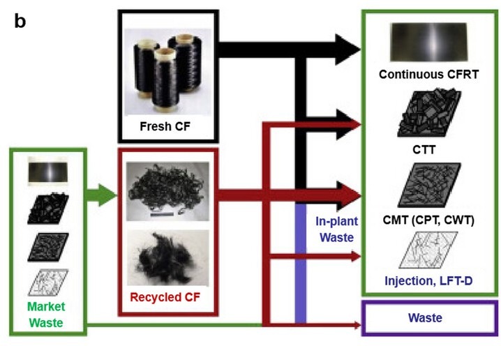
- Recycled fiber feedstock
- Embodied energy reuse
- 50% lower cost vs. virgin CF
- Competes on affordability
The chopped tape (CTT) architecture is worth highlighting for its strategic importance to the recycling economy. CTTs can be produced from manufacturing waste — the review specifically cites Gulfstream G650 elevator and rudder offcuts from GKN Fokker being reprocessed into access door panels with stiffening ribs and variable wall thickness. A part that would otherwise be landfilled becomes structural feedstock. For manufacturers under ESG pressure, this is a compelling circular economy story.
Processing Routes: Where the Decisions Get Made
Seven core processing methods are reviewed, each with distinct cost, rate, and geometry tradeoffs:

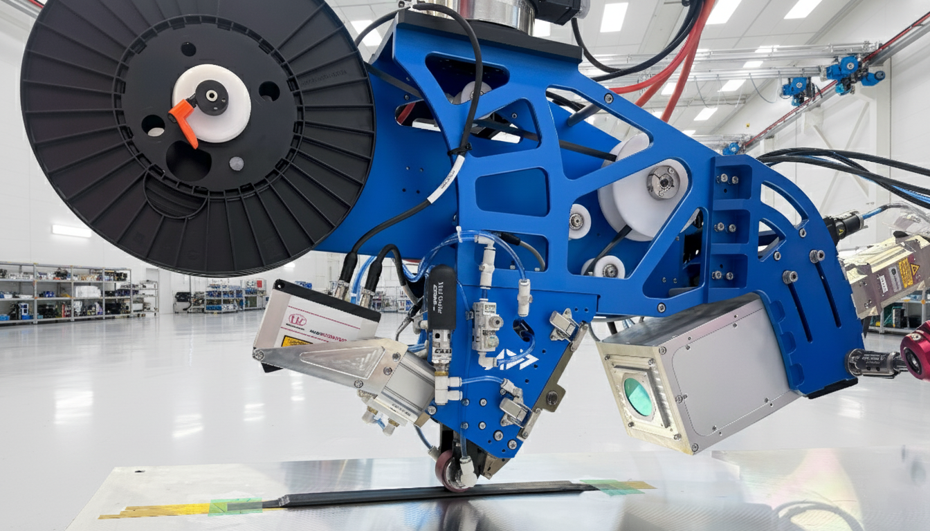
NIR laser heats the thermoplastic tape at the nip point while the consolidation roller bonds it to the substrate in a single pass.

AFP-XS head mid-laydown: laser heating zone visible at the nip point during in-situ consolidation of carbon fiber thermoplastic tape. Image: Addcomposites.
Process Engineering · Selection Logic
CFRT Processing Decision Tree
Select the right process by geometry — hover each card for specs
- In-situ or post-consolidation (OOA)
- Laydown: 0.5–2 m/s
- Resolution: ±0.30 mm
- Pressure: 2.5 MPa
- Feed: 30–80 m/h
- L-, U-, T-, J-, I-profiles
- Airbus + Boeing qualified
- No post-processing required
- In-situ consolidation at nip point
- H₂ storage: Type III–V vessels
- 70 MPa working pressure demonstrated
- Cycle time: minutes
- Heat above Tm / Tg → quench in tool
- Floor beams, brackets, ribs
- Organosheet + short fiber injection
- Cycle time: ~60 s
- Automotive body-in-white
- CF cap: ~20 wt%
- Continuous fiber: in-situ or ex-situ fusion
- LCFT pellets, short fiber compounds
- Complex geometries, thin walls
- Automotive exterior / interior trim


Welding: The Capability That Changes Everything
This is the section of the review that most directly disrupts conventional CFRP program economics — and the section that receives the least attention in standard composite training.
Thermoset CFRP structures are joined with mechanical fasteners. Every fastener is a hole in the laminate (stress concentration), a metallic insert (weight penalty), a labor operation (cost), and a maintenance point. A typical commercial aircraft fuselage section uses tens of thousands of fasteners.
Thermoplastic welding eliminates the fastener. The thermoplastic matrix, when heated above its melting point under pressure, achieves molecular chain entanglement across the interface — producing a joint indistinguishable from the bulk material. The review surveys four industrially relevant techniques:
Thermoplastic Joining · Process Comparison
Welding Method Comparison
Four thermoplastic welding technologies — heat source, capability, and MFFD deployment
The MFFD Proof-of-Concept
The Multifunctional Fuselage Demonstrator upper shell was produced by DLR using AFP for skin lay-up, robotic ultrasonic welding for stringer integration, and resistance welding for frame and cleat attachment. The target: 70–100 aircraft per month, €1 million per-fuselage cost reduction, 1,000 kg weight reduction versus the A321 ACF. GKN Fokker led the lower shell under the STUNNING project.

The assembly of the fuselage halves used a butt-strap longitudinal joint on one side and ultrasonic welding on the opposing side — fastener-free, continuous, and automated.
Pressure Vessels: The Hydrogen Economy Opens a New Front
The review dedicates substantial treatment to CFRT composite pressure vessels (CPVs) for hydrogen storage — a market driven by fuel cell electric vehicles and single-aisle aircraft using liquid or cryo-compressed hydrogen.
The CPV market for gas and liquid storage represents 8% of global CFRP demand, with carbon fiber production capacity targeted to grow by more than 20%. The hierarchy of CPV types (I through V) tracks a clear progression from full-metal to full-composite construction, with weight, fatigue resistance, and volumetric capacity all improving as composite content increases.

Type IV vessels (plastic liner, full composite overwrap) already power the Toyota Mirai and Honda Clarity at 70 MPa. Type V — no liner at all, composite as both structure and gas barrier — represents the next frontier, eliminating liner-composite strain incompatibility and reducing weight by a further 10–20%.
CFRT tape winding (TTW) is the primary manufacturing route for CPVs, processing CF-PA12 tape for ground transport and CF-PAEK systems for higher-performance aviation applications. The in-situ consolidation achieved during winding means no secondary autoclave step — a significant cycle time and cost advantage over thermoset filament winding.

Schematic of the thermoplastic tape winding (TTW) process. Wang et al., Advanced Materials, 2025, 37, 2418709. CC-BY 4.0.

AFP-XS winding thermoplastic carbon fiber tape onto a cylindrical mandrel with in-situ consolidation — no autoclave step required. Image: Addcomposites.
The Recycling Imperative
One of the clearest strategic arguments for CFRTs over thermosets is also one of the least discussed: what happens at end of life.
The review maps the European waste hierarchy — prevention, reuse, repurposing, recycling, recovery, disposal — against the actual options available to CFRP operators. Thermosets offer only the lower tiers: mechanical grinding, energy recovery, or landfill. Thermoplastics can be remelted, reformed, and reused in structural applications.

The commercial precedent already exists. TenCate and GKN Fokker demonstrated this in 2016: scrap from Gulfstream G650 elevator and rudder production (Cetex TC1100 CF/PPS) was reprocessed into access door panels with integral stiffening ribs, bosses, and variable thickness. Less virgin material, thinner and lighter parts, at lower cost.
The Economics of Recycled Carbon Fiber
Recycled carbon fiber costs approximately 50% less than virgin fiber — a compelling economics argument even before considering regulatory pressure toward circular manufacturing.
Where Addcomposites Sits in This Transition
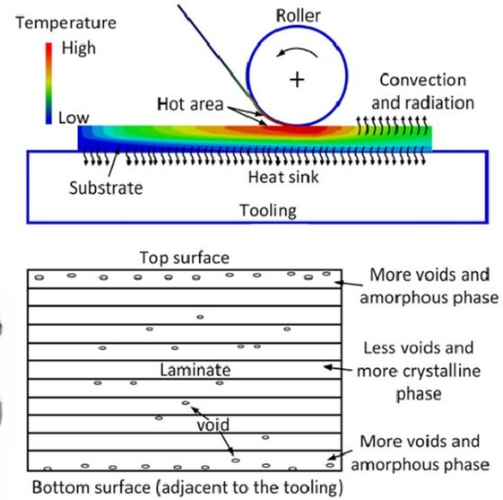
Nip-point temperature distribution (top) and resulting void/crystallinity gradient through the laminate thickness (bottom) during thermoplastic AFP — the key process variables that determine in-situ consolidation quality without autoclave post-processing. Wang et al., Advanced Materials, 2025, 37, 2418709. CC-BY 4.0.
The AFP-XS system is designed precisely for the manufacturing inflection point this review describes. Thermoplastic AFP is not an incremental upgrade to thermoset AFP — it is a fundamentally different process, requiring tighter control of nip-point temperature, compaction force, and laydown speed to achieve in-situ consolidation without secondary autoclave steps.
The review's data on LATP (laser-assisted tape placement) is directly relevant: temperature, pressure, and speed are all adjustable to achieve in-situ consolidation, and CO₂ lasers (10.6 μm wavelength) are specifically suited to LMPAEK because standard fiber lasers at 1,060 nm are not efficiently absorbed by the polymer matrix. The MFFD's lower shell AFP used exactly this configuration.
At current ISC speeds of 60–100 mm/s, thermoplastic AFP is competitive for fuselage structures without secondary processing steps. Larger, thicker structures (wings) still benefit from post-consolidation, but the trajectory is clearly toward full in-situ consolidation as process robustness improves.
Thermoplastic AFP · Process Readiness
Where In-Situ Consolidation Is Competitive Today
Current ISC capability boundaries for thermoplastic AFP — fuselage geometries vs. thick primary structure
For programs where cycle time and fastener elimination are the primary drivers — short-range aircraft, UAVs, pressure vessels, automotive structural inserts — thermoplastic AFP with in-situ consolidation is not a future capability. It is available now.
The Roadmap Ahead
The review's conclusion section identifies several clear vectors for thermoplastic CFRT development over the next decade:
Materials
Thicker tapes (up to 0.18 mm) are in demand. Hybrid semicrystalline/amorphous polymer architectures are being developed to maintain processing flexibility without sacrificing final crystallinity. Surface treatment of carbon fiber for thermoplastic compatibility remains an underinvested area — epoxy sizings designed for thermosets are still the default, limiting interface quality in CFRT applications.
Processing
Fiber steering in AFP — optimizing fiber orientation for complex shapes beyond standard 0°/45°/90° layups — is an active development area. OOA forming and coconsolidation are being extended to complex spars, beams, and integrally stiffened skins. In-situ process monitoring and control are critical to reducing the current reliance on coupon-level process development before scaling to production.
Joining
Current leakage issues in resistance welding need systematic resolution. Continuous ultrasonic welding for large structures requires further optimization of velocity and energy parameters. Laser welding of CFRT-to-CFRT remains a challenge due to carbon fiber's absorption and reflection of laser energy.
Recycling
Large-scale commercial recycling of CFRT manufacturing waste — beyond the proof-of-concept level demonstrated by GKN Fokker — is the next frontier. The MFFD project's use of injection-molded short fiber blends from production scrap points toward a closed-loop model that will become increasingly important as regulatory requirements tighten.
What This Means for Your Program
The Wang et al. review does not argue that thermoset CFRP is finished — for highly loaded primary structures with complex geometry and no production rate pressure, autoclave-cured thermoset remains the performance-per-cost optimum today. What the review makes clear is the trajectory: thermoplastic CFRTs are gaining ground in every sector where production rate, recyclability, weldability, or room-temperature storage matter — which is most of the growth in the CFRP market over the next two decades.
Wind energy already consumes more carbon fiber than aerospace. Electric vehicles are driving automotive CFRP demand into territory that thermoset cycle times cannot serve. Hydrogen storage is an entirely new market with no incumbent thermoset position. And even in aerospace, the MFFD project has demonstrated that fully thermoplastic fuselage structures are not hypothetical.
The manufacturers who commit to thermoplastic AFP infrastructure now will have the process knowledge, the certified material databases, and the weld-joining capabilities that will define competitive advantage as these markets mature.
Source Note
This post is based on: Wang H.H., Huo S., Chevali V., Hall W., Offringa A., Song P., Wang H. "Carbon Fiber Reinforced Thermoplastics: From Materials to Manufacturing and Applications." Advanced Materials, 2025, 37, 2418709. DOI: 10.1002/adma.202418709. Open Access under CC-BY 4.0. Data on specific properties, processing parameters, and application examples cited throughout this post are drawn directly from the above publication. Additional context on AFP-XS capabilities reflects Addcomposites' product documentation.
Learn More
Ready to explore thermoplastic AFP for your program? The AFP-XS is available now for in-situ consolidation of PEEK, PEKK, LMPAEK, and PPS tapes — no autoclave required.
Get in TouchReferences
- Wang H.H., Huo S., Chevali V., Hall W., Offringa A., Song P., Wang H. "Carbon Fiber Reinforced Thermoplastics: From Materials to Manufacturing and Applications." Advanced Materials, 2025, 37, 2418709. DOI: 10.1002/adma.202418709. Open Access under CC-BY 4.0.
