When Geometry Does the Heavy Lifting: A New CFRP Crash Box Design That Outperforms Metal by Several Times Over
How a sun-shaped carbon fiber structure — validated by a novel 50%-faster simulation workflow — is rewriting the rulebook on automotive crash energy absorption.
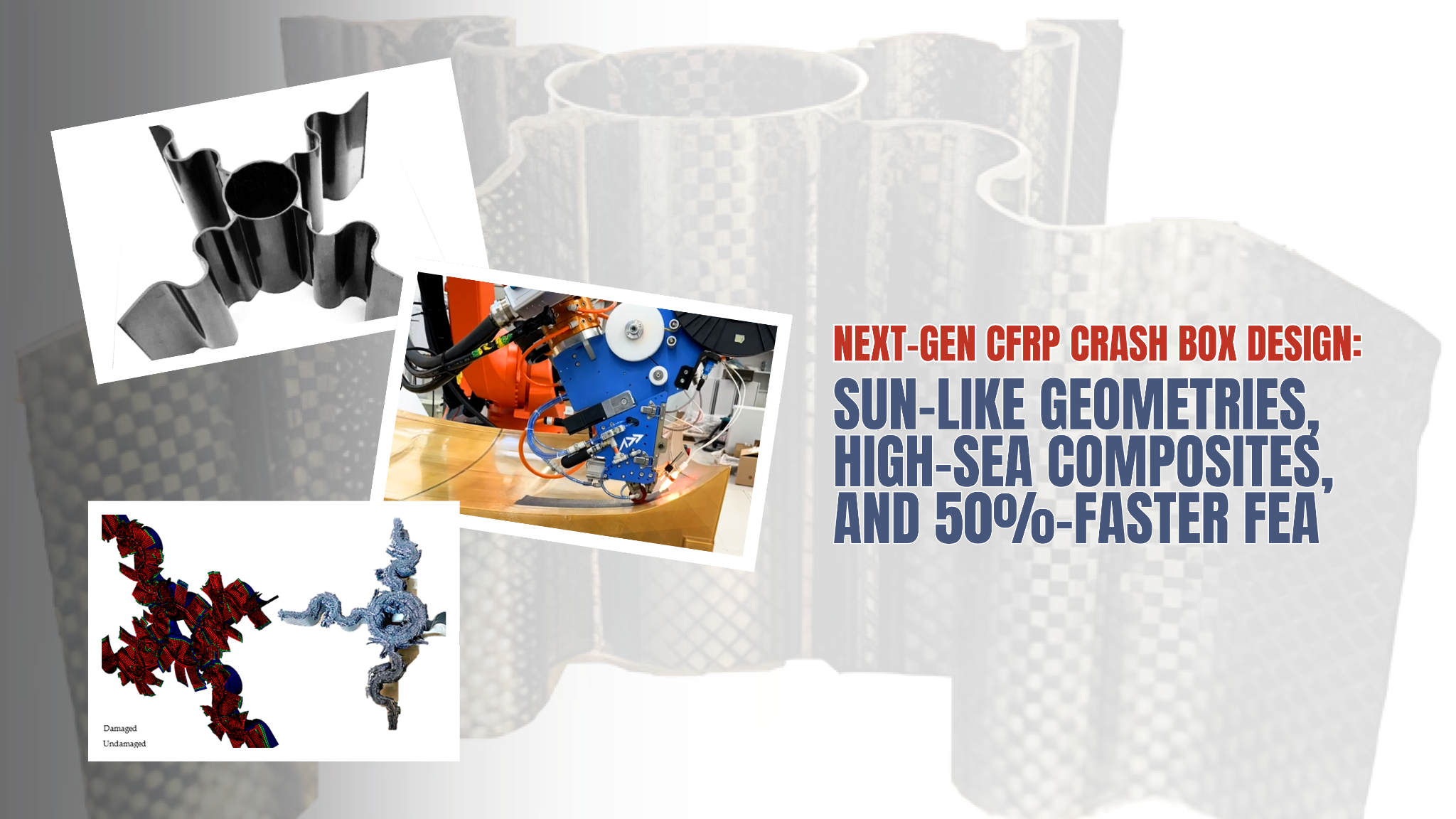
Crash boxes occupy a narrow band of a vehicle's front structure, but the engineering demands placed on them are anything but narrow. They must collapse predictably under axial load, absorbing the maximum possible kinetic energy before a crash event reaches the main frame — and they must do all of this while weighing as little as possible. For decades, the industry has relied on steel and aluminium, accepting specific energy absorption (SEA) values in the 15–30 J/g range as the ceiling. A February 2026 open-access paper published in Journal of Composites Science (MDPI) by Engul, Demir, and Ersoy from Boğaziçi University, Virginia Tech, and Yildiz Technical University challenges that ceiling head-on — and clears it by a factor of three to four.
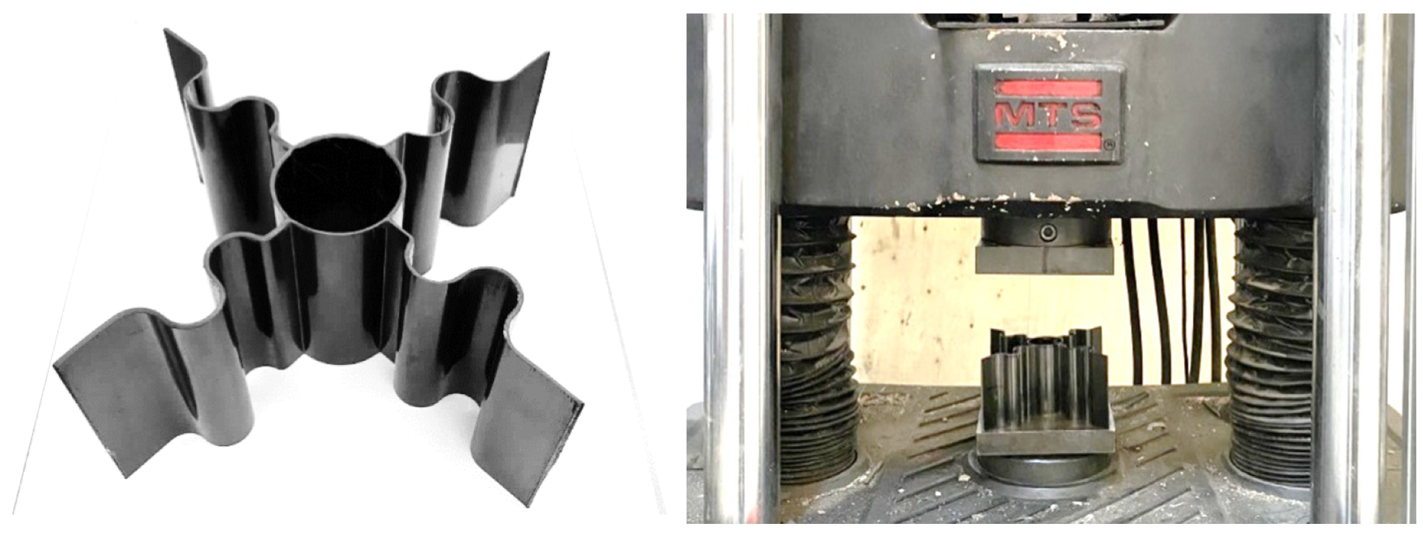
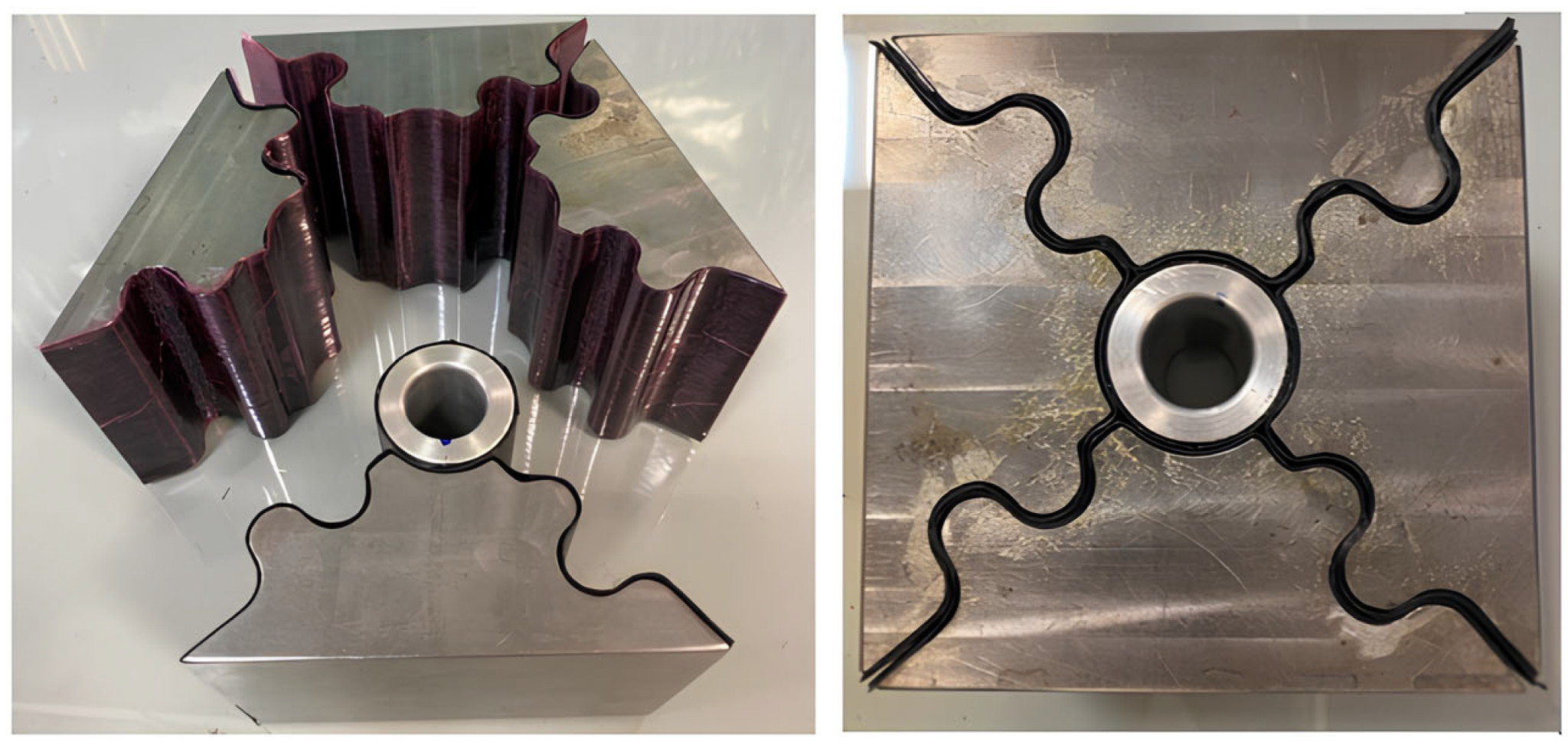
The manufactured SL4 sun-like crash box (left) and the MTS
hydraulic test setup with specimens under axial compression
(right).
Figure 19 from: Engul, M.; Demir, S.; Ersoy, N. "Design,
Manufacturing, and Analysis of a Carbon Fiber Reinforced
Polymer Crash Box." Journal of Composites Science 2026, 10,
85.https://doi.org/10.3390/jcs10020085
— © 2026 by the authors. Licensed under CC BY 4.0 (https://creativecommons.org/licenses/by/4.0/).
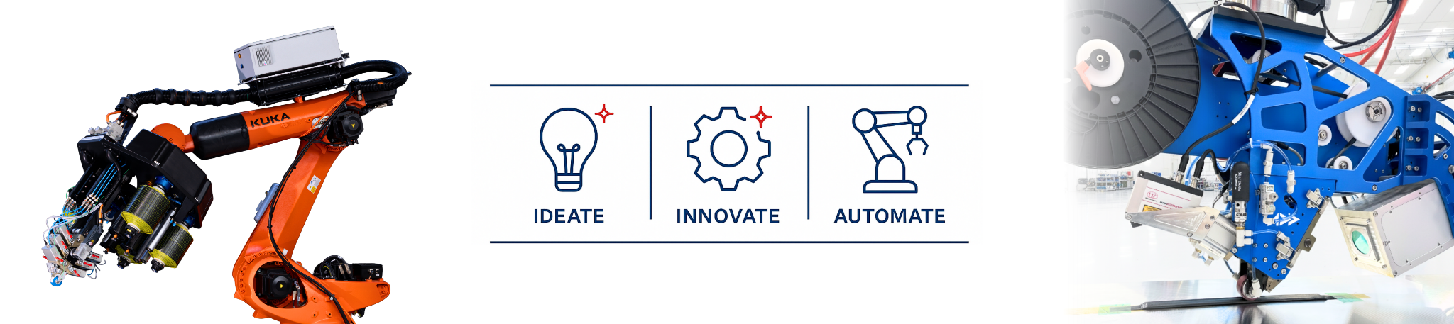
This post walks through what the paper actually shows, why the geometry matters so much, how the authors solved the computational bottleneck that makes CFRP crash box design so expensive, and what all of this means for composite manufacturers investing in automated fibre placement (AFP) platforms.
The Core Problem: Why CFRP Crash Box Design Is Hard
Designing a metallic crash box is relatively tractable: material behaviour under axial crush is well characterised, and finite element (FE) simulations run in reasonable time. CFRP is a different story. The failure mechanics — intralaminar fibre and matrix cracking, interlaminar delamination, debris wedge formation, and their interactions — are simultaneously active and deeply coupled. FE models that capture all of this are accurate but extremely slow, which makes iterative geometry exploration by trial-and-error manufacturing both time-consuming and expensive.
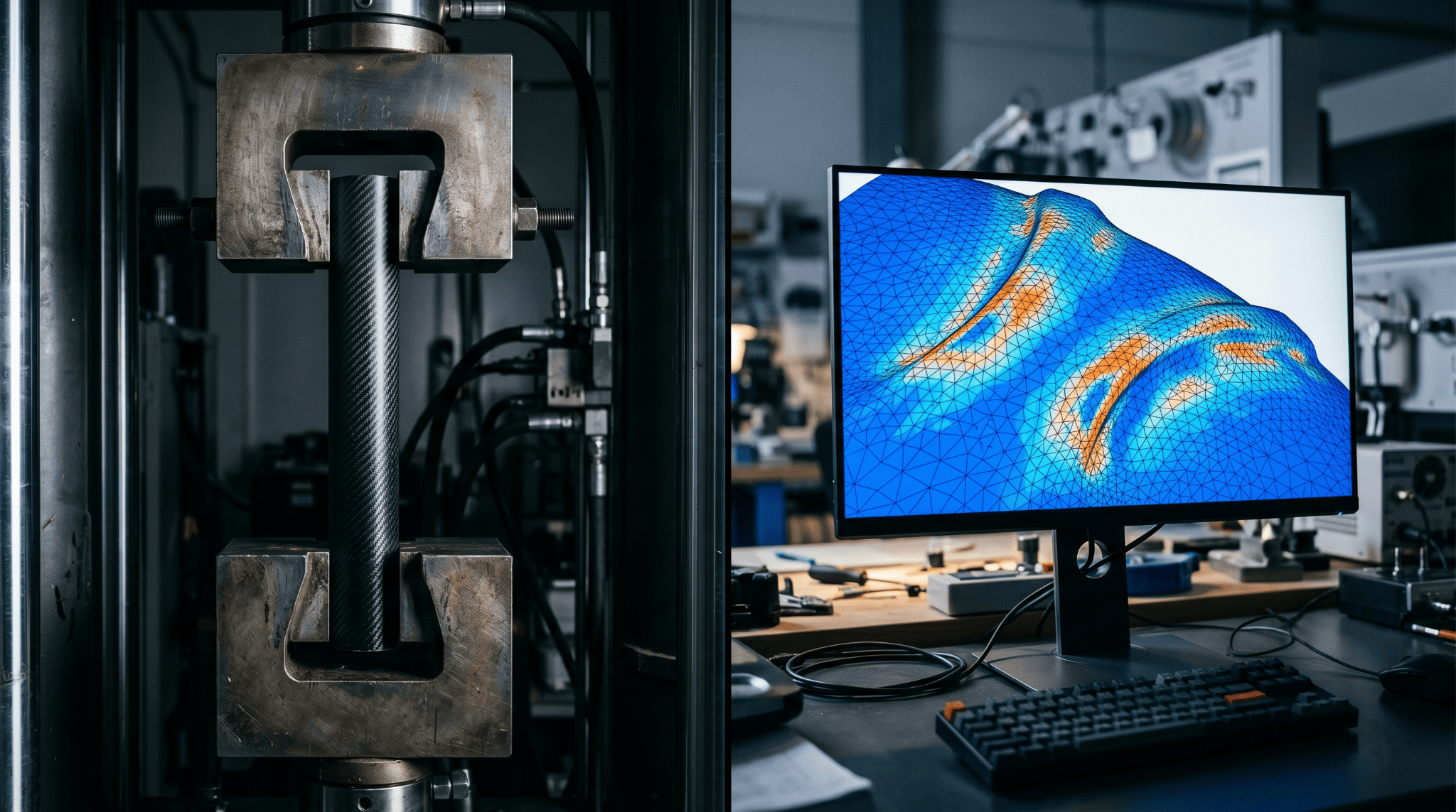
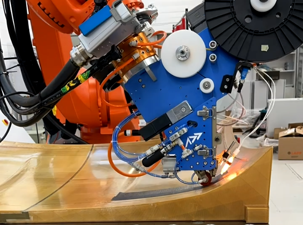
AI-generated illustration for representational purposes. Physical compression testing (left) and finite element simulation (right) — the two bottlenecks in iterative CFRP crash box design.
The paper addresses this with a novel reduced-interface modelling strategy, then applies it to design a genuinely new crash box geometry. The two contributions — faster simulation and better geometry — reinforce each other: you cannot easily explore a large design space if each candidate takes hours to simulate.
The Numerical Methodology: Halving Simulation Time Without Losing Fidelity
The modelling approach, originally developed by the same group for flat cross-ply laminates, works by consolidating the individual plies of a [0/90]₂ₛ laminate into four [0/90] sub-laminates rather than modelling all eight individual plies separately. This reduces the number of cohesive interfaces from seven to three.
Reducing interfaces saves computation, but it also changes how energy is dissipated through delamination — so the material properties must be recalibrated. The authors' procedure involves:
- Three-point bending reference models on individual 0° and 90° plies, then on the consolidated sub-laminate, to measure how much energy dissipation is lost in the consolidation step.
- Halving in-plane parameters for the cross-ply sub-laminates to compensate for reduced intralaminar energy paths.
- Doubling fracture toughness values to restore total delamination energy, and increasing interfacial strength by 41% to maintain cohesive zone length.
The net result, validated against previously published experimental data on sinusoidal specimens with three and five curvatures, is summarised below:
Simulation Accuracy vs. Run-Time: Novel vs. Conventional FE
SEA error vs. experiment: <2% in both cases · Data: Table 2, Engul et al., J. Compos. Sci. 2026, 10, 85
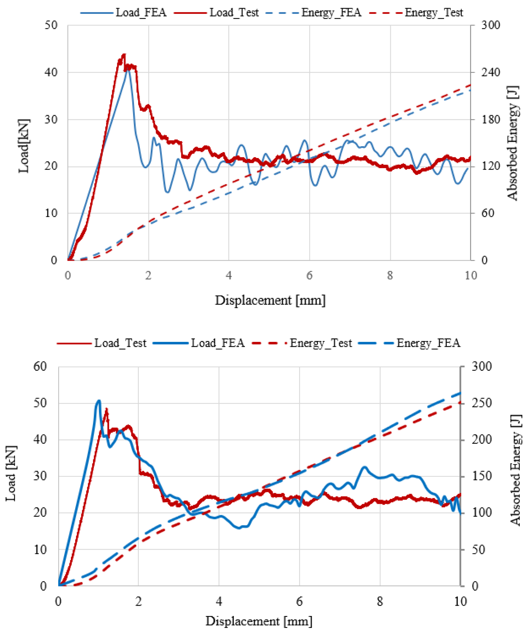
Load–displacement curves (solid lines) and cumulative absorbed
energy curves (dashed lines) for sinusoidal CFRP specimens with 3
curvatures (top) and 5 curvatures (bottom), with the novel FE
model prediction plotted against experimental test data. The close
tracking of both curve shapes across the full 10 mm crush distance
confirms the methodology preserves progressive crushing behaviour,
not just the final SEA number.
Figure 4 from: Engul, M.; Demir, S.; Ersoy, N. "Design,
Manufacturing, and Analysis of a Carbon Fiber Reinforced Polymer
Crash Box." Journal of Composites Science 2026, 10, 85.
https://doi.org/10.3390/jcs10020085
— © 2026 by the authors. Licensed under CC BY 4.0 (
https://creativecommons.org/licenses/by/4.0/).
The SEA predictions remain within roughly 2% of experimental measurements while cutting wall-clock simulation time nearly in half. From a design-iteration standpoint, this is not a minor efficiency gain — it is the difference between running two geometry candidates per day and running four or five.
Addcomposites' Perspective
For AFP-equipped manufacturers developing crash structures, simulation throughput is a genuine bottleneck. Coupling this methodology with parametric AFP layup planning means geometry candidates can be evaluated faster, and the layup parameters that drive fibre orientations, thickness buildups, and tow-steering radii can be adjusted between loops without waiting for overnight FE runs.
Three Geometries, One Winner
Armed with a validated fast-simulation workflow, the authors evaluated three progressively more complex crash box designs, all built from AS4/8552 carbon/epoxy unidirectional (UD) prepregs in a [0/90]₂ₛ configuration. The design logic starts from a well-established finding in the authors' prior work: among flat, semi-circular, and sinusoidal geometries, a sinusoidal plate with five curvatures of 9 mm radius delivers the highest SEA.
The three candidates combine that sinusoidal building block in different configurations:
Cross-Section Taxonomy of the Three Candidate Crash Box Designs
Dimensions from Table 3, Engul et al., J. Compos. Sci. 2026, 10, 85
Dimensions from Table 3, Engul et al., J. Compos. Sci. 2026, 10, 85
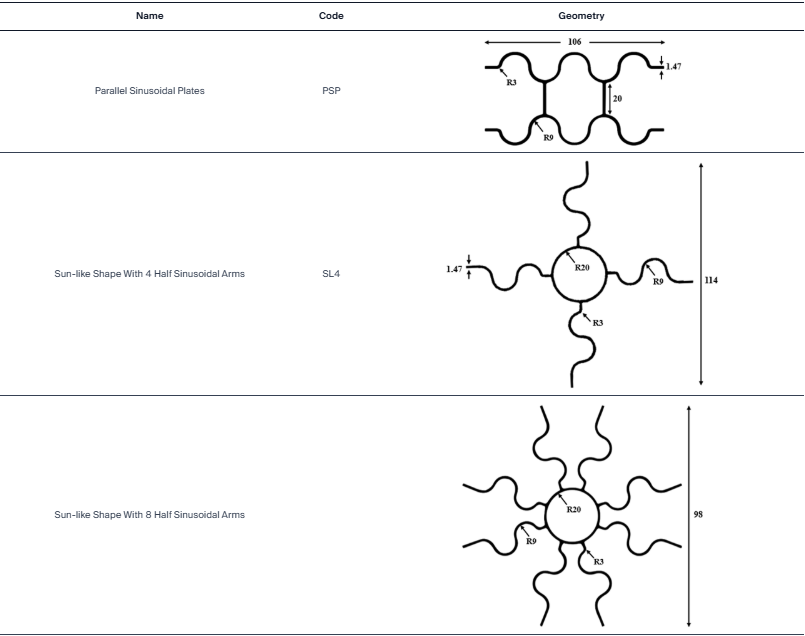
Dimensioned cross-sectional drawings of the three candidate
crash box designs: PSP (top) combining two sinusoidal plates
with flat vertical connecting walls across a 106 mm width; SL4
(centre) with a central circular core of R20 mm and four
sinusoidal half-arms of R9 mm radius extending to a 114 mm
envelope; SL8 (bottom) with eight sinusoidal half-arms on the
same R20 core within a tighter 98 mm envelope. Wall thickness
is 1.47 mm throughout.
Table 3 from: Engul, M.; Demir, S.; Ersoy, N. "Design,
Manufacturing, and Analysis of a Carbon Fiber Reinforced
Polymer Crash Box." Journal of Composites Science 2026, 10,
85.https://doi.org/10.3390/jcs10020085
— © 2026 by the authors. Licensed under CC BY 4.0 (https://creativecommons.org/licenses/by/4.0/).
This post walks through what the paper actually shows, why the geometry matters so much, how the authors solved the computational bottleneck that makes CFRP crash box design so expensive, and what all of this means for composite manufacturers investing in automated fibre placement (AFP) platforms.
The paper's FE results explain the performance hierarchy clearly. In the PSP design, the flat walls connecting the two sinusoidal plates contribute relatively little to energy dissipation — matrix damage is largely absent in those central flat sections — which caps the SEA improvement over a single sinusoidal plate. The SL4 design replaces those flat walls with a circular core, and the simulation shows increased vertical rupture, micro-buckling, and fibre fracture in the circular region as a result. Among all the failure modes active during CFRP crush — delamination, matrix cracking, micro-buckling — fibre breakage consumes the most energy per unit volume, so any geometry that maximises that mode gains disproportionately in SEA. The SL8 design adds a further four arms, and the denser arm spacing does push more fibre failure into the T-joint zones, generating incremental energy gains. But those gains plateau quickly: the T-joint material reaches fracture saturation early, and packing in additional arms cannot compensate once that zone is exhausted.
Numerical SEA Results — All Four Geometries
Specific Energy Absorption, crushed over 10 mm · Data: Table 4, Engul et al., J. Compos. Sci. 2026, 10, 85
Data from Table 4, Engul et al., J. Compos. Sci. 2026, 10, 85
The paper reports that SL4 achieves a 16% higher SEA per unit mass than the single sinusoidal baseline, while SL8 reaches a 20% gain — both measured numerically over a 10 mm crush distance. But the authors chose SL4 for physical manufacture. The reasoning is worth noting: between the two sun-like designs, the energy absorption difference is modest, while the manufacturing difference is not. The SL4 geometry requires fewer mould parts, a simpler lay-up procedure, and produces fewer opportunities for defects. This is exactly the trade-off that advanced manufacturing programmes face constantly — and it is one where AFP technology changes the calculus.
Taming the Peak Load: The Role of Edge Tapering
Even a crash box with excellent average SEA can cause passenger injury if its initial peak load is too high. An abrupt force spike at the onset of crush produces a deceleration pulse that may exceed what occupant restraint systems can safely handle. The paper examines a straightforward geometric countermeasure: a 5° taper applied to each sinusoidal arm beginning at the T-joint and widening outward, converting each arm into a truncated cone.
Load vs. Displacement: Tapered vs. Non-Tapered SL4
Interpretive schematic derived from Figure 16, Engul et al., J. Compos. Sci. 2026, 10, 85
Interpretive schematic — exact curve shapes vary from the paper figure
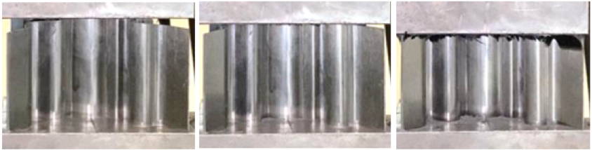
Sequential photographs of the tapered SL4 carbon fibre crash
box at four stages of quasi-static axial compression, from
undeformed through to approximately 10 mm of crush travel. The
gradual, stable progression of the crush front — with no
catastrophic collapse or global buckling — confirms that the
5° taper successfully converts the abrupt initial load spike
into a controlled, progressive failure sequence.
Figure 22 from: Engul, M.; Demir, S.; Ersoy, N. "Design,
Manufacturing, and Analysis of a Carbon Fiber Reinforced
Polymer Crash Box." Journal of Composites Science 2026, 10,
85.
https://doi.org/10.3390/jcs10020085
— © 2026 by the authors. Licensed under CC BY 4.0 (https://creativecommons.org/licenses/by/4.0/)
The FE results are unambiguous. Rather than spiking to an early peak, the tapered configuration distributes resistance more progressively — the force profile climbs steadily across approximately the first 3 mm of crush travel instead of lunging abruptly to its maximum. The mean crushing load after that initial phase remains essentially the same as the non-tapered geometry, because the material being crushed — and the energy dissipation mechanisms — are unchanged beyond the taper zone.
Experimentally, the tapered UD geometry measured an SEA of 78.63 J/g — negligibly lower than the non-tapered average of 79.46 J/g — confirming that eliminating the peak load costs almost nothing in total energy absorption. The governing reason: the amount of material removed by tapering is proportional to the reduction in absorbed energy, so the ratio (energy per gram) stays nearly constant.
The Material Upgrade: Woven Fabric Prepregs Push SEA to 89.26 J/g
The tapered SL4 crash box made from plain weave carbon/epoxy
prepregs after quasi-static axial crushing. The extensive
fragmentation visible across all four sinusoidal arms — small
debris pieces rather than intact peeled fronds — is
characteristic of woven fabric failure under axial crush, and
is the direct mechanical reason the WF specimens achieve a
higher SEA than their unidirectional equivalents on the same
geometry.
Figure 25 from: Engul, M.; Demir, S.; Ersoy, N. "Design,
Manufacturing, and Analysis of a Carbon Fiber Reinforced
Polymer Crash Box." Journal of Composites Science 2026, 10,
85.
https://doi.org/10.3390/jcs10020085
— © 2026 by the authors. Licensed under CC BY 4.0 (https://creativecommons.org/licenses/by/4.0/)
With the SL4 geometry established as the preferred design, the authors took a second pass using woven fabric (WF) prepregs — specifically KOM10T/PL200 plain weave 3K T300 carbon/epoxy supplied by KORDSA — in place of the UD material. Six plies at 0.21 mm cured thickness each replaced the eight UD plies, achieving a wall thickness of 1.26 mm (slightly thinner than the 1.47 mm UD wall).
The textile structure of woven fabric changes the crushing morphology. According to the paper, the higher SEA of WF prepregs on this geometry stems from the yarn architecture: the interlocking fibres promote breakage-dominated failure rather than the splaying behaviour more characteristic of UD laminates. In practical terms, this translates to measurably higher SEA.
The three UD compression tests returned 78.30, 79.10, and 80.98 J/g respectively, averaging 79.46 J/g (σ = 0.95 J/g) — tight scatter confirming good test repeatability. Switching to WF prepregs on the same geometry pushed that average to 89.26 J/g: a 12.4% improvement attributable purely to material selection, and cumulatively about 30% ahead of where the single sinusoidal plate sits. The FE model for the WF case, using the ABQ_PLY_FABRIC built-in subroutine and the Cohesive Zone Method for interlaminar damage, predicted 91.21 J/g — within 2.2% of the experimental mean, a level of agreement the authors characterise as strong.
Experimental SEA Summary — UD vs. WF SL4 Crash Box
Specific Energy Absorption per test specimen · Data: Sections 4 and 5, Engul et al., J. Compos. Sci. 2026, 10, 85
σ = 0.95 — consistent results
Single specimen reported
Best performer across all variants
Data from Sections 4 and 5, Engul et al., J. Compos. Sci. 2026, 10, 85
Manufacturing Reality: What It Takes to Build a Sun-Like Shape
The paper does not gloss over production complexity. The SL4 geometry requires a steel-block split-die mould cut to shape via wire EDM, a machining method chosen for the precision required by the sinusoidal arm profile. The mould comprised four curved parts for the arm surfaces and a cylindrical central insert for the core. Hand lay-up was used: a [0/90/0/90] ply sequence was built up on the arm-mould surfaces while a mirrored [90/0/90/0] sequence was laid onto the cylindrical centre insert — producing the symmetric cross-ply stack across the full geometry. After vacuum bagging and autoclave curing, specimens were cut to 50 mm length and edge-chamfered. Tapering used a diamond disc cutter followed by emery paper finishing.
The steel split-die mould assembly with unidirectional
carbon/epoxy prepreg plies draped over the sinusoidal arm surfaces
and cylindrical central insert, prior to vacuum bagging and
autoclave curing.
Figure 18 from: Engul, M.; Demir, S.; Ersoy, N. "Design,
Manufacturing, and Analysis of a Carbon Fiber Reinforced Polymer
Crash Box." Journal of Composites Science 2026, 10, 85.
https://doi.org/10.3390/jcs10020085
— © 2026 by the authors. Licensed under CC BY 4.0 (https://creativecommons.org/licenses/by/4.0/)
For high-volume or high-consistency manufacturing, hand lay-up on this geometry presents real challenges: the sinusoidal arm surfaces involve compound curvature, the T-joint regions require careful ply book-matching, and any fibre misalignment in the arm structure will affect local stiffness and crush trigger behaviour.
Addcomposites' Perspective
This is precisely where AFP changes what is possible. The AFP-XS and associated plug-and-produce AFP head units are designed to handle continuous tow placement over curved mandrel surfaces, including sinusoidal and multi-lobe geometries. Tow steering allows fibre orientations in the arm regions to be optimised locally — for instance, aligning fibres to maximise fibre fracture contribution in the curvature zones, which the paper identifies as the highest-SEA-generating regions. The result is not just faster production, but the ability to produce geometries like SL4 with consistent, defect-free fibre placement that hand lay-up cannot reliably replicate at scale.
The Addcomposites AFP-XS head unit in operation, depositing tow over a curved surface. Precision fibre placement at tight radii — the manufacturing capability that hand lay-up cannot reliably replicate at scale.
Furthermore, for AFP-capable programmes exploring WF alternatives, the higher SEA of woven fabric materials must be weighed against the reduced drapability of woven prepregs on tight-radius sinusoidal surfaces. Tow-steered UD tape, placed by AFP with controlled tension, may ultimately offer the best compromise between geometric conformance and energy absorption on arm radii as tight as the 9 mm featured here.
Why Geometry Matters More Than You Think: The Damage Mechanics Argument
One of the more illuminating aspects of the paper is its use of FE damage visualisation to explain why the SEA hierarchy exists — not just that it does. The PSP geometry's flat central walls generate no matrix damage during crushing, because they are loaded primarily in membrane rather than bending compression. That means those regions contribute relatively little to the total energy budget. The T-joints, by interrupting crack propagation paths, force the structure to generate more fibre fracture rather than propagate clean delamination fronts — but those gains are partly offset by the flat wall inefficiency.
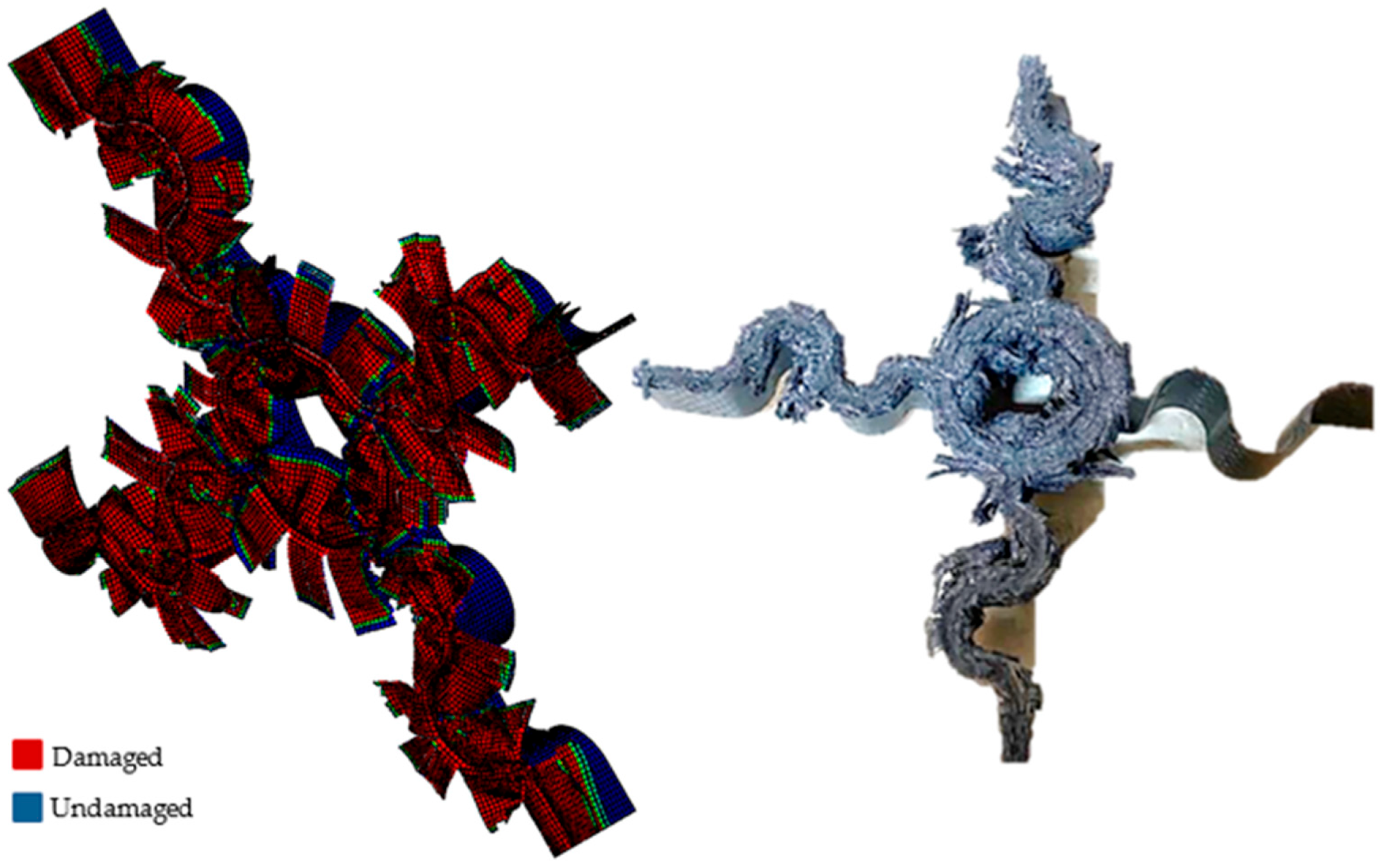
In the SL4 and SL8 designs, the circular core is loaded in a combination of hoop compression and local bending, generating matrix cracking, micro-buckling, and fibre fracture across a much larger fraction of the total crushed volume. The paper tracks the number of elements reaching fibre failure thresholds across designs: SL4 produces more fibre-failed elements than PSP, which is the mechanistic explanation for its higher SEA rather than a coincidental correlation.
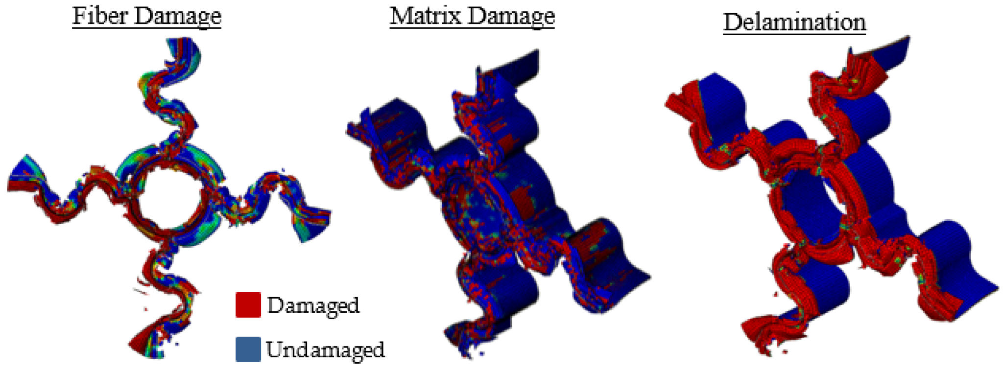
FE simulation damage maps for the SL4 geometry after axial
crushing: fibre failure concentrated near the contact zone and
circular core (left), matrix failure across the sinusoidal arm
sidewalls (centre), and delamination propagating outward from the
T-joints (right). Red indicates damaged elements; blue indicates
undamaged material.
Figure 11 from: Engul, M.; Demir, S.; Ersoy, N. "Design,
Manufacturing, and Analysis of a Carbon Fiber Reinforced Polymer
Crash Box." Journal of Composites Science 2026, 10, 85.
https://doi.org/10.3390/jcs10020085
— © 2026 by the authors. Licensed under CC BY 4.0 (https://creativecommons.org/licenses/by/4.0/)
This damage-mechanism framing matters for design: it tells the engineer which geometric features are earning their mass, and which are not. Flat walls in a crash box — regardless of material — are mass-inefficient. Curved features in biaxial compression are where composite crush energy absorption is generated.
The SEA Ceiling and What Lies Beyond
To situate these results in context, the paper's comparison with metallic crash boxes is worth stating plainly: metallic structures typically achieve 15–30 J/g. The UD SL4 design reaches 79.46 J/g experimentally — roughly 2.6 to 5.3 times that range. The WF SL4 reaches 89.26 J/g. These are not marginal improvements; they represent a qualitative shift in what a crash structure can deliver per unit mass.
SEA Performance Ladder: Material and Geometry Progression
Each rung represents a design decision — geometry or material — and its SEA gain
Based on Tables 2, 4, and Section 5 of Engul et al., J. Compos. Sci. 2026 · Metallic range from Introduction, citing [1] and [2] therein
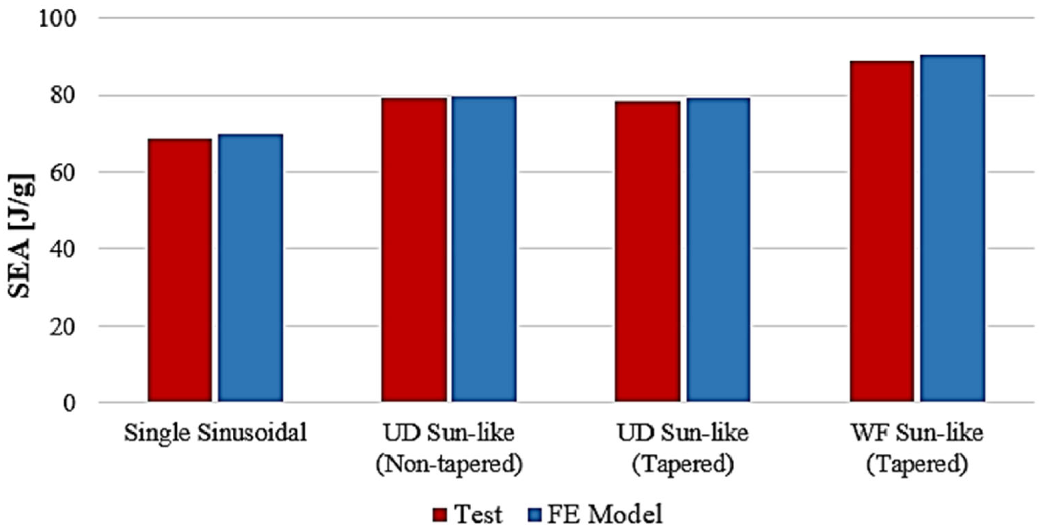
Bar chart comparing specific energy absorption values from
experimental tests and FE model predictions across all four
configurations: single sinusoidal baseline, UD sun-like
non-tapered, UD sun-like tapered, and WF sun-like tapered. Each
paired bar set shows test result alongside FE model estimate, with
the consistently small gap between them confirming predictive
accuracy across all geometry and material combinations tested.
Figure 26 from: Engul, M.; Demir, S.; Ersoy, N. "Design,
Manufacturing, and Analysis of a Carbon Fiber Reinforced Polymer
Crash Box." Journal of Composites Science 2026, 10, 85.
https://doi.org/10.3390/jcs10020085
— © 2026 by the authors. Licensed under CC BY 4.0 (https://creativecommons.org/licenses/by/4.0/)
The paper notes that while the SL8 geometry achieves 82.55 J/g numerically — marginally above SL4's 79.70 J/g — the manufacturing complexity tips the balance toward SL4 as the practical optimal. This is an important signal for programmes evaluating the SL8 path: the diminishing returns on additional arms set in early because T-joint fibre fracture saturates. Adding more arms past four is not the most efficient way to continue climbing the SEA curve. Material selection (UD to WF) and taper optimisation appear to offer larger, more accessible gains.
What This Means for AFP-Equipped Composite Manufacturers
Engul, Demir, and Ersoy's work points toward a set of conclusions that have direct bearing on how composite crash structures should be designed and manufactured:
Geometry Is the Highest-Leverage Variable
The SL4 geometry achieves roughly 2.6× the SEA of metallic crash boxes, and 16% more than the best single sinusoidal plate — gains driven entirely by cross-section architecture, not material change. For AFP programmes, this means the first investment should go into developing and manufacturing complex geometries precisely — not simply sourcing a higher-spec prepreg.
Sinusoidal Arm Features Require Precision Manufacture
The 9 mm arm radii in the SL4 design are tight. The FE model's SEA predictions assume consistent ply placement and correct crush trigger behaviour — both of which are sensitive to fibre orientation accuracy in the curvature zones. AFP enables exactly this kind of controlled, repeatable placement.
Faster Simulation Unlocks Iterative Design
The reduced-interface FE methodology cuts simulation time roughly in half with less than 2% SEA error. Pairing this with parametric AFP process planning allows the design-simulate-manufacture loop to run far more efficiently — more geometry candidates evaluated, more quickly.
Tapering Is a Near-Zero-Cost Safety Feature
Adding a 5° edge taper to SL4 eliminates the initial peak load with less than 1% penalty to SEA. For any programme where occupant deceleration limits are a certification concern, this is a straightforward structural countermeasure confirmed by both simulation and experiment.
WF Prepregs Offer a Real SEA Premium
The 12.4% SEA gain from switching to woven fabric on the SL4 design is significant and experimentally well-supported. AFP manufacturers working with woven tow or woven tape variants — or considering hybrid UD/WF layup sequences — have a validated data point to work from.
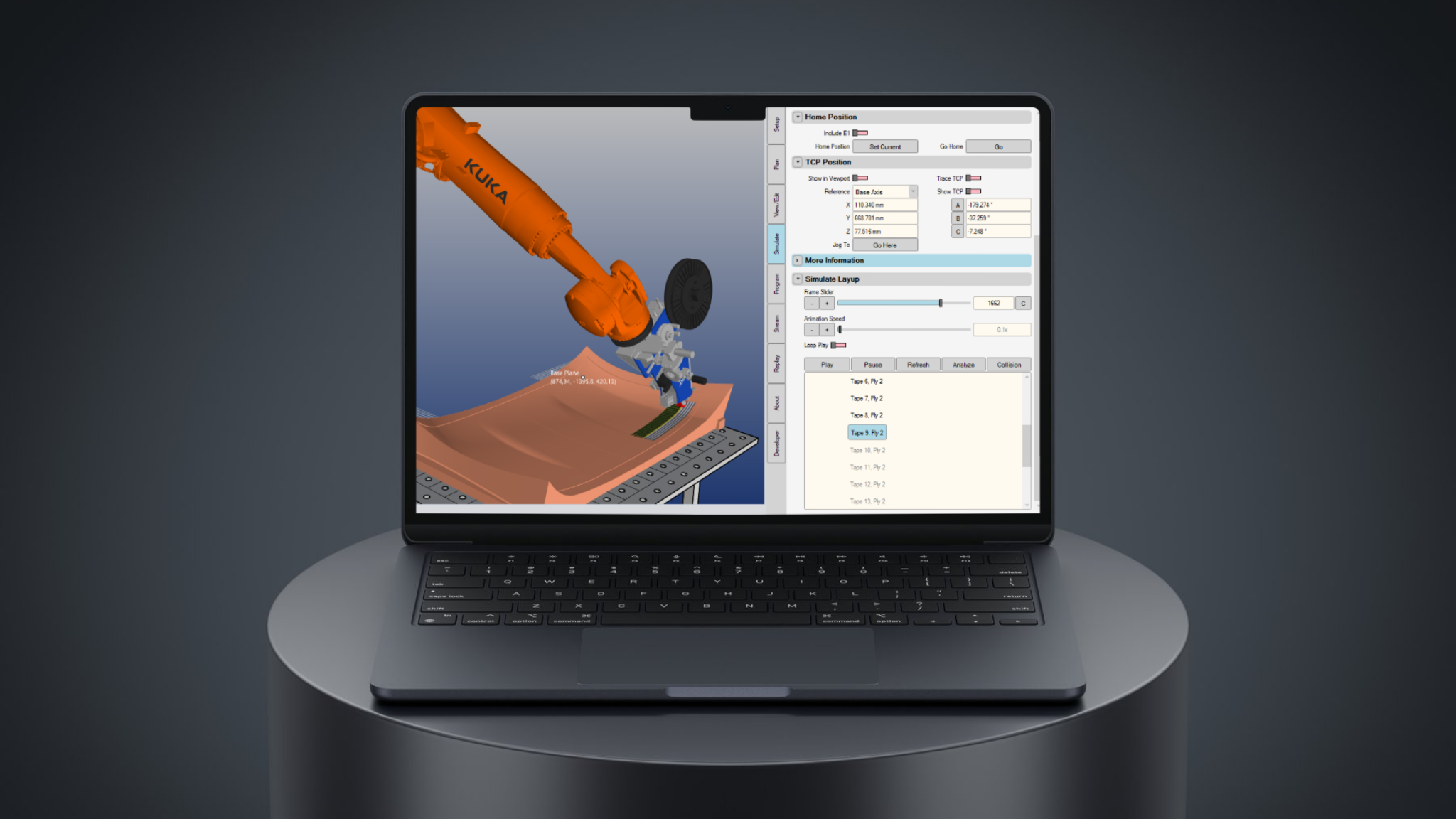
AddPath software simulating the AFP layup sequence over a curved geometry — the process planning layer that connects FE design iterations to physical manufacture.
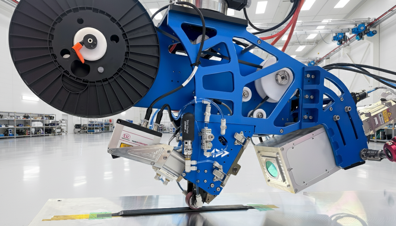
The Addcomposites AFP-XS head unit — precision tow placement hardware designed for R&D and low-to-mid volume composite production environments.
Addcomposites' AFP-XS platform, designed for rapid deployment in R&D and low-to-mid volume production environments, is well-positioned to support exactly this kind of iterative crash structure development: complex sinusoidal and multi-lobe mandrel geometries, tow-steered UD placement, and the process consistency that makes FE model assumptions valid in practice. The research reviewed here gives manufacturers a clear geometry target, a validated simulation shortcut, and a material comparison — the manufacturing execution is where AFP makes the difference.
Read the Research
This post draws entirely on the following open-access paper. All data, figures referenced, and methodology described originate from this source. The authors of the paper have no affiliation with Addcomposites and have not reviewed or endorsed this post.
Learn More
Get in touch to discuss your composite crash structure or AFP application →
Contact Us for a ConsultationReferences
- Engul, M.; Demir, S.; Ersoy, N. "Design, Manufacturing, and Analysis of a Carbon Fiber Reinforced Polymer Crash Box." Journal of Composites Science 2026, 10, 85. https://doi.org/10.3390/jcs10020085 Published: 6 February 2026. Open access under Creative Commons Attribution (CC BY) 4.0 license. https://creativecommons.org/licenses/by/4.0/
This post draws entirely on the open-access paper cited above. All data, figures, and methodology described originate from that source. The authors of the paper have no affiliation with Addcomposites and have not reviewed or endorsed this post.