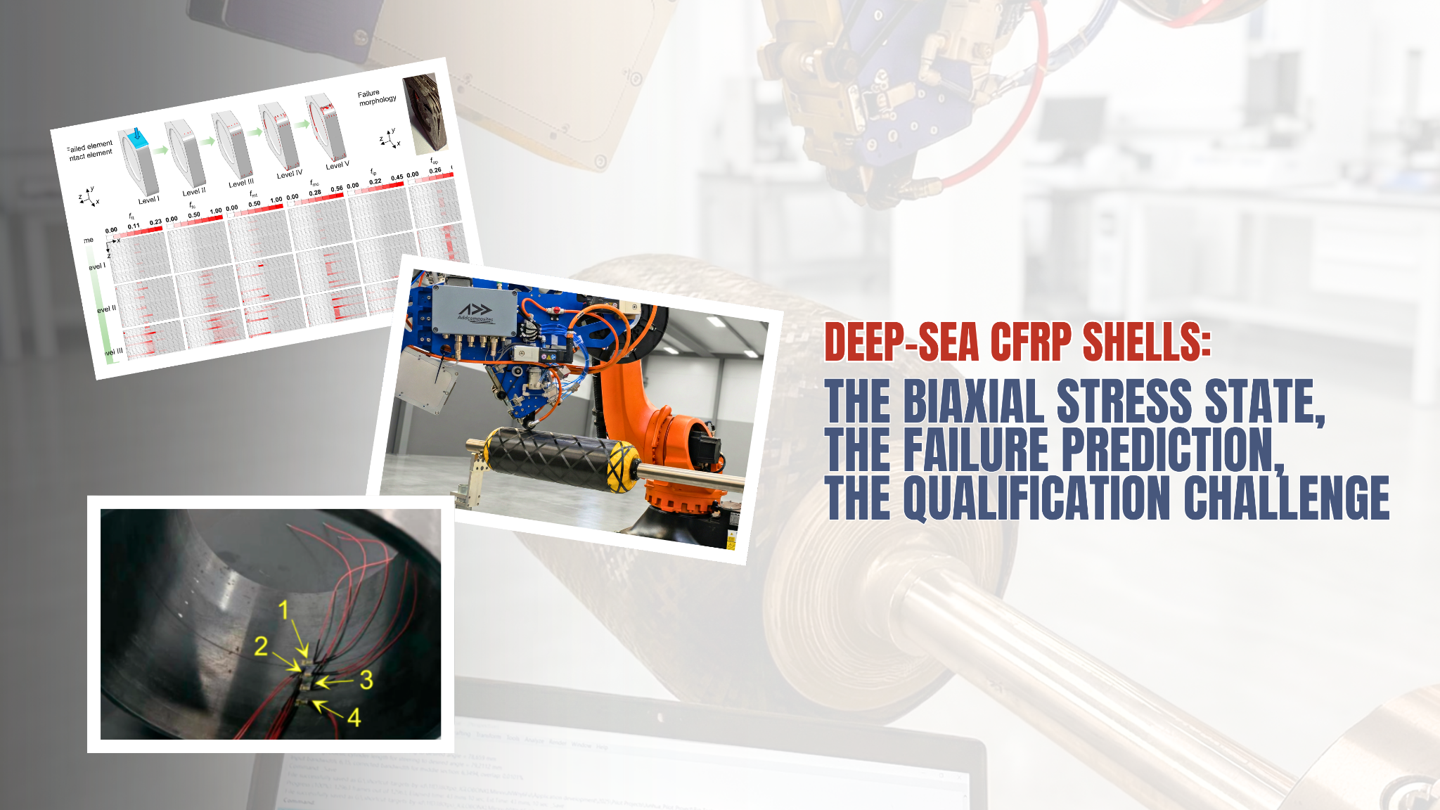
Your Deep-Sea CFRP Shell Is Weaker Than Your Test Data Says: You're Testing It in One Direction
A composite pressure hull on the seabed is never loaded in a single direction. Hydrostatic pressure squeezes it from every side at once, generating substantial compressive stresses in both the circumferential (hoop) and axial directions simultaneously. Yet the qualification data behind most CFRP shell designs comes from uniaxial compression coupons — specimens crushed along one axis at a time. A February 2026 open-access study in the Journal of Composites Science makes the gap between those two worlds uncomfortably concrete: measured biaxial compressive strength came in far below the uniaxial value in the same direction, by roughly a third to nearly two-thirds depending on the loading case.
For anyone manufacturing CFRP cylindrical shells for autonomous underwater vehicles, manned submersibles, gliders, or deep-sea instrument housings, that is not an academic footnote. It means a laminate qualified against uniaxial data may carry less load at depth than the test report implies.
This post walks through what the study tested, what it found, and where precise layup control fits into designing for the stress state that actually exists on the seafloor.
A note on sourcing
Everything attributed to "the paper," "the study," or "the authors" below is drawn from Zhou et al., Journal of Composites Science 2026, cited in full at the end. Sections marked "Our perspective" are Addcomposites' own commentary and are not claims made by, or endorsed by, the paper's authors. The paper itself does not use, mention, or evaluate Addcomposites or its products.
The problem: a hull lives in a biaxial world
The authors frame the engineering motivation clearly. A pressure shell under external hydrostatic load does not see one dominant stress; it sees a combined circumferential-and-axial compressive field, with comparatively low radial stress. On a metal shell of the same shape, pressure works the hoop direction about twice as hard as the axial one. The study points out that uniaxial loading tests, however well understood, cannot reliably predict how a composite behaves once two compressive stresses act together.
That mismatch is the whole story. The authors observe that earlier multiaxial work has leaned toward tension cases, which leaves the all-compression loading a deep-sea shell actually sees comparatively under-studied. The contribution of this work is to close part of that gap with a two-pronged verification strategy: biaxial compression tests on flat laminate coupons, paired with a hydrostatic pressure test on a full cylindrical shell.
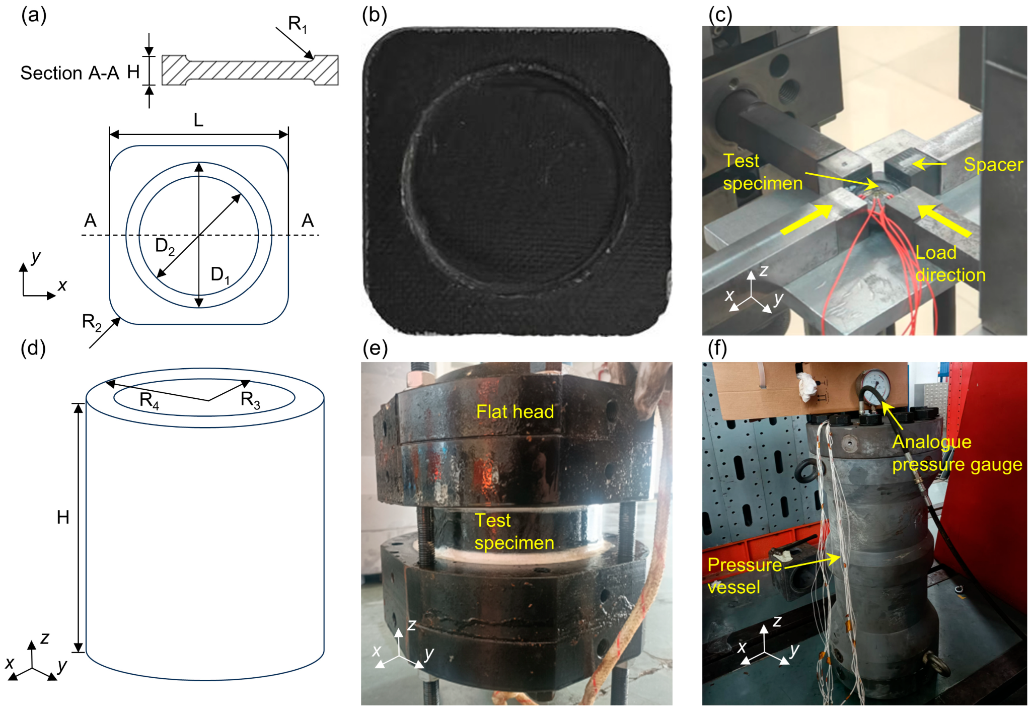
The cruciform biaxial compression specimen (schematic and photograph), the Zwick Z050 biaxial test rig in operation, the wet-wound composite cylindrical shell with steel end-cap assembly (schematic and tooling photograph), and the sealed hydraulic pressurization testbed used for the hydrostatic failure test. Figure 2 from: Zhou, C.; Tang, Z.; Deng, X.; Gao, Y.; Jiang, H. "Strength and Failure Behavior of Carbon Fiber Composite Laminates Under Biaxial Compression for Deep-Sea Application." Journal of Composites Science 2026, 10, 130. https://doi.org/10.3390/jcs10030130 — © 2026 by the authors. Licensed under CC BY 4.0.
What was tested, and how it was built
The laminate in question uses a stacking sequence written as [90°/90°/90°/20°/−20°] repeated and made symmetric about the midplane. Here the 90° direction is the circumferential one. The layup is deliberately lopsided: three hoop plies for every pair of shallow off-axis plies. The authors' rationale is that if the hoop direction carries about twice the stiffness of the axis, both directions strain by similar amounts and the fiber pulls its weight in each. For this stack, that lands at a hoop-to-axial modulus ratio near 1.78.
Layup and Stiffness Asymmetry
hoop-dominant stiffness
Addcomposites visualization of layup and stiffness data reported in Zhou et al., J. Compos. Sci. 2026.
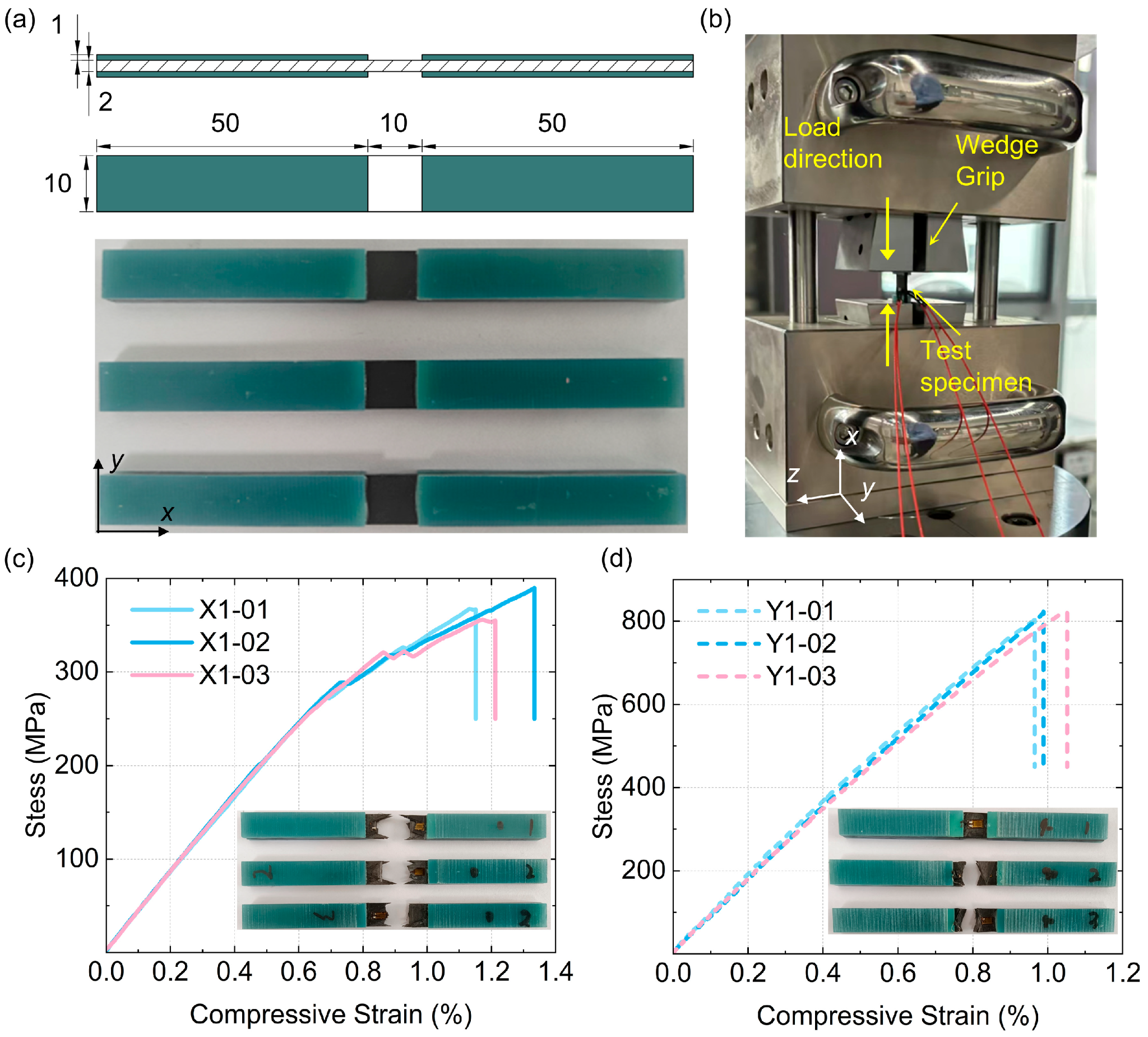
Uniaxial compression specimens with tabbed ends (dimensions and photograph), the wedge-grip compression testbed, and stress–strain curves from three repeated tests in the 0° axial direction (X1, peak ~371 MPa) and the 90° circumferential direction (Y1, peak ~817 MPa), with inset photographs of the respective failure modes. Figure 1 from: Zhou, C.; Tang, Z.; Deng, X.; Gao, Y.; Jiang, H. "Strength and Failure Behavior of Carbon Fiber Composite Laminates Under Biaxial Compression for Deep-Sea Application." Journal of Composites Science 2026, 10, 130. https://doi.org/10.3390/jcs10030130 — © 2026 by the authors. Licensed under CC BY 4.0.
Both the coupons and the shell used a T700 carbon fiber/epoxy system with a fiber volume fraction of about 60% and a nominal ply thickness near 0.2 mm. The flat coupons were produced by prepreg compression molding; the cylindrical shell was made by wet winding carbon fiber and epoxy. The longitudinal modulus of the unidirectional lamina is reported as 138 GPa, with a transverse modulus of 8.55 GPa, an in-plane shear modulus of 4.46 GPa, and a major Poisson's ratio of 0.31. On the strength side, the lamina shows a longitudinal tensile strength of 2110 MPa against a longitudinal compressive strength of 1337 MPa, and a stark transverse asymmetry: 24.5 MPa in transverse tension versus 140 MPa in transverse compression. The test program covered three regimes: uniaxial compression along each in-plane axis; biaxial compression in two flavors; and a stepped hydrostatic pressure test on the shell. The biaxial coupons were run on a cruciform biaxial rig under two protocols — equal-displacement control (driving comparable strain in both directions) and a 1:2 proportional-force protocol intended to mimic the roughly 2:1 hoop-to-axial stress split of a real pressure shell. Three valid specimens were tested per condition and the reported numbers are the means.
The uniaxial baseline: direction matters a lot
Before the biaxial story, the uniaxial coupons set a reference. Crushed along the axial (0°, x) direction, the laminate reached an average peak stress of 371 MPa. Crushed along the circumferential (90°, y) direction, it reached 817 MPa — about 2.2 times higher.
Uniaxial Compressive Strength
Consistent with the layup's three 90° plies per repeat unit, concentrating fibre-direction load capacity circumferentially.
The authors attribute the difference to the layup itself. The y-direction is rich in 90° plies that are well aligned to carry that load, so its response stays nearly linear up to failure. The x-direction leans on the matrix and on the shallow ±20° plies, which tend to shear and slide between layers when compressed, so it gives way sooner and at a much lower stress. That asymmetry is intentional and useful for a hoop-dominated shell — but it also means the two directions behave by very different mechanisms, which becomes important once both are loaded together.
The headline result: two directions at once is worse than one
Here is the finding that matters most for design. Under both biaxial protocols, the ultimate compressive strength in a given direction fell well below the uniaxial value in that same direction.
Uniaxial vs Biaxial Compressive Strength
The reductions are not uniform — they range from about 36% in the best case (axial direction, equal-displacement) to roughly 64% in the worst (hoop direction, equal-displacement). The single "40% weaker" figure that sometimes gets attached to this work is, at best, a rough midpoint; the honest version is a band that depends heavily on which direction and which loading path you care about. The same downward trend showed up in failure strain as well as strength.
The authors read it as a stress-state effect: two compressive axes at once start matrix damage sooner and let it grow, so the fibers never deliver their full strength before the laminate lets go. In other words, the second axis of compression doesn't just add a bit of stress; it changes when and how the laminate begins to come apart.
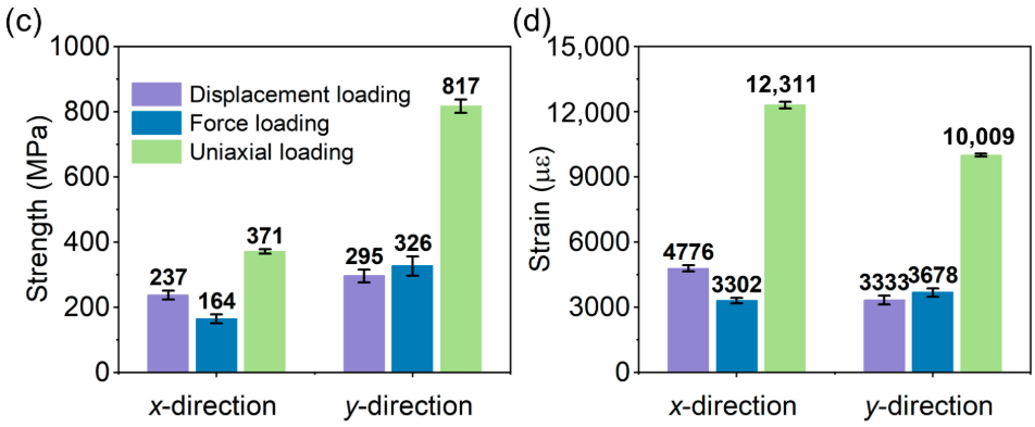
Grouped bar charts showing compressive strength (MPa) and failure strain (µε) for both x- and y-directions under three loading conditions — uniaxial, equal-displacement biaxial, and 1:2 proportional-force biaxial — with error bars at ±1 SD, making the stepwise strength reduction from uniaxial to biaxial loading visible in both axes simultaneously. Figure 4 (panels c and d) from: Zhou, C.; Tang, Z.; Deng, X.; Gao, Y.; Jiang, H. "Strength and Failure Behavior of Carbon Fiber Composite Laminates Under Biaxial Compression for Deep-Sea Application." Journal of Composites Science 2026, 10, 130. https://doi.org/10.3390/jcs10030130 — © 2026 by the authors. Licensed under CC BY 4.0.
Our perspective
The design implication is the part worth dwelling on. If a deep-sea shell is qualified against uniaxial coupon data and a knockdown factor that wasn't derived from biaxial testing, the margin sitting in the design file may be smaller than it looks. The study's value for a manufacturer is less "the number is X" and more "the shape of the failure surface under compression is not what a uniaxial test will tell you."
Which failure criterion should you actually trust?
Knowing biaxial strength is lower is only half the battle. To design a shell, you need a failure criterion in your finite element model that predicts that lower value accurately. The study implemented six classical and enhanced criteria as three-dimensional user-material subroutines (written in Fortran for Abaqus/Explicit) and benchmarked each against the biaxial coupon data: maximum stress, maximum strain, Tsai–Wu, Rationalized Tsai–Wu, Hashin, and Shokrieh.
The verdict was consistent across the program: Hashin tracked the measurements most closely across the board.
Absolute % Error vs Experiment
A few things stand out. In the hoop direction, Hashin landed within 2.6% of the measured strength, and most criteria did reasonably well there. The axial direction was harder for every criterion — even the best result carried about 15% error — which tracks with the matrix- and shear-driven failure mechanism that makes that direction messy in the first place. The authors note that Tsai–Wu reads a little high on strength, while the maximum-stress, maximum-strain, R-Tsai–Wu, and Shokrieh criteria generally come in conservative. Under the 1:2 proportional-force protocol, the failure-strain comparison told the same story, with Hashin predicting the measured strains to within roughly 1 to 2%.
Our perspective
The practical takeaway is that criterion choice is not cosmetic. Picking Shokrieh over Hashin for this layup could shift a predicted strength by 20 percentage points or more, which is the difference between a shell that passes review and one that doesn't. For a design team, the study reads as an argument for validating your chosen criterion against representative biaxial data rather than inheriting a default from a uniaxial workflow.
How the damage actually develops
Because Hashin came out ahead, the authors used it to trace how damage evolves through an equal-displacement biaxial test. The picture is a progression rather than a single event.
Damage Progression
Damage appeared first on the hoop-loaded surface, then at the matching location on the axial-loaded surface; the two zones grew, merged, and finally formed a band through the thickness. Crucially, when the first element was removed in the simulation, the fiber-tension damage coefficient sat at only 0.23 — so fiber tension was not what drove failure. Fiber compression, concentrated in the 20° plies and their mirrored counterparts, was far more severe and approached the limit. Matrix tension developed in those same plies and reached its initiation criterion as displacement increased, but because fiber-direction failure had not yet occurred, the coupon kept carrying load rather than failing catastrophically right away. The authors report that the model's failed-element map matched where cracks actually appeared on the specimens, both beginning at the edges and migrating toward the middle.
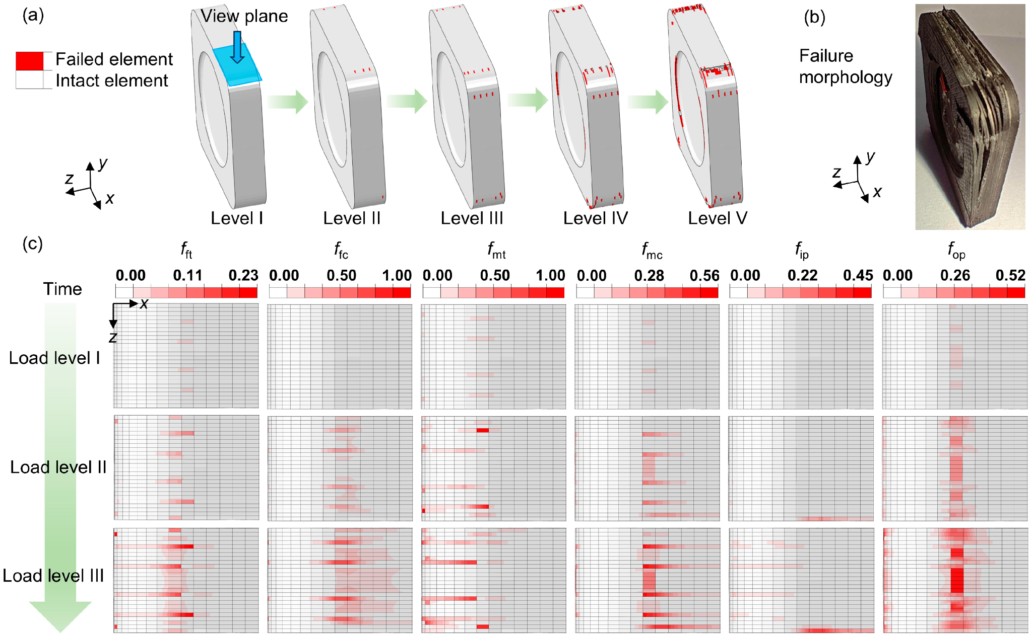
Five-stage FEM damage contour sequence showing red failed elements initiating at the specimen edges and merging into a through-thickness band (panel a), a photograph of the physically fractured cruciform specimen with the corresponding damage band visible (panel b), and an 18-map grid tracking six individual damage-mode coefficients — fiber tension, fiber compression, matrix tension, matrix compression, in-plane shear, and out-of-plane shear — across three successive load levels, with fiber compression the dominant mode approaching its limit (panel c). Figure 5 from: Zhou, C.; Tang, Z.; Deng, X.; Gao, Y.; Jiang, H. "Strength and Failure Behavior of Carbon Fiber Composite Laminates Under Biaxial Compression for Deep-Sea Application." Journal of Composites Science 2026, 10, 130. https://doi.org/10.3390/jcs10030130 — © 2026 by the authors. Licensed under CC BY 4.0.
Scaling up: the shell test
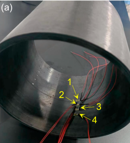
The carbon-fiber-wound interior surface of the composite cylindrical shell with four numbered strain-gauge clusters bonded along the axial centerline, each carrying one circumferential and one axial gauge, spaced from the shell center outward at 0, 15, 30, and 45 mm. Figure 6 (panel a) from: Zhou, C.; Tang, Z.; Deng, X.; Gao, Y.; Jiang, H. "Strength and Failure Behavior of Carbon Fiber Composite Laminates Under Biaxial Compression for Deep-Sea Application." Journal of Composites Science 2026, 10, 130. https://doi.org/10.3390/jcs10030130 — © 2026 by the authors. Licensed under CC BY 4.0.
Instrumentation and pressurization protocol
The flat-coupon results are only convincing if they carry over to a real cylinder, so the authors built and pressurized a wet-wound shell with the same family of layup (the hoop-heavy sequence repeated four times and made symmetric). It was fitted with steel end caps, sealed with O-rings, and pressurized in 2 MPa steps inside a sealed hyperbaric vessel.
Because the shell could not be observed directly inside the vessel, failure was inferred from the pressure history and strain gauges. At 22 MPa, a loud report sounded inside the cabin and the pressure began to fall — the shell had failed. The Hashin-based simulation predicted collapse at 20.75 MPa, within 5.7% of the test.
The simulated damage initiated on the outer surface near the strain-gauge point about 30 mm off-center, close to the end cap, and then spread to a global collapse — matching where post-test inspection found the damage. The extracted failure strains at that location were 3,938 µε axially and 3,039 µε circumferentially. Set against the laminate's uniaxial failure strains of 12,311 µε and 10,009 µε, those in-service numbers are lower by roughly 68 to 70%. That single comparison is, in many ways, the most vivid statement of the paper's thesis: the strain a shell can actually tolerate in its working stress state is a small fraction of what a one-directional coupon test would suggest.
Shell Failure Pressure & Failure Strain
The authors are candid about the study's limits. The simulations are macroscale, so they don't resolve individual constituent-level flaws — porosity, off-angle fibers, patchy resin wet-out, uneven cure — though those effects are folded into the measured material inputs. And the criteria evaluated are existing formulations rather than new ones; the authors flag refinement and further validation as future work.
Our perspective: where layup control enters the picture
Everything above is the paper's. What follows is Addcomposites' own reading, and it is worth restating that the authors did not use Addcomposites equipment or software and make no claims about it.
The through-line of the study is that the laminate's behavior under biaxial compression is governed by its architecture — the ratio of hoop to off-axis plies, the precise off-axis angle, and the symmetry of the stack. The hoop direction was strong because it was deliberately fiber-rich; the axial direction was the weak link precisely because it leaned on the matrix and on shallow off-axis plies that shear and slide. Change those angles or that ratio and you change both the stiffness split and where damage starts.

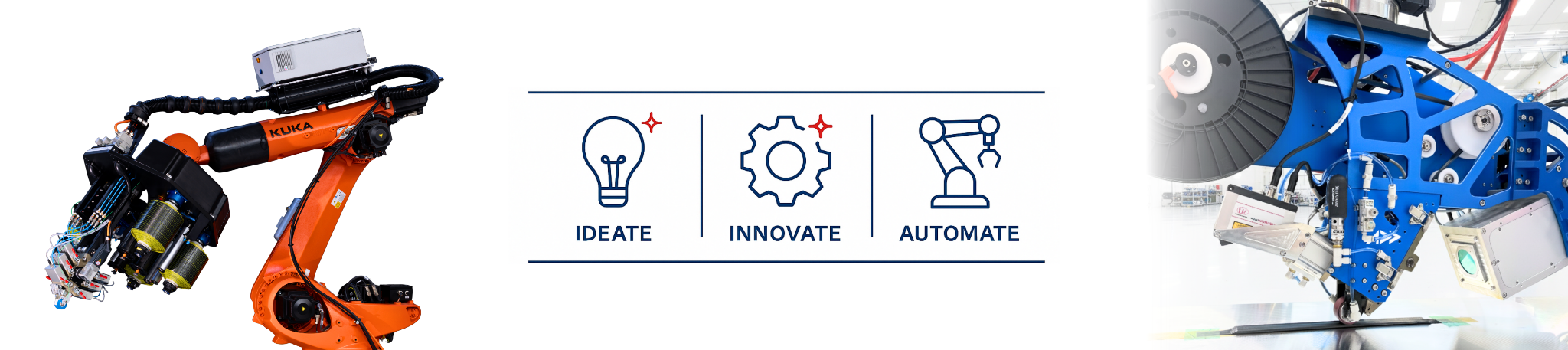
The Addcomposites AFP-XS head in winding configuration on a KUKA robotic arm, with the off-axis carbon fiber winding pattern visible on the cylindrical mandrel below.
AFP and filament winding: one platform
That is exactly the design variable that automated manufacturing exists to control, and it maps onto the Addcomposites toolset more directly than it might first appear. The shell in this study was made by wet winding, which is a job our AFP-XS and AFP-X heads are built to do: both are configurable either as automated fiber placement systems or as filament winding systems, running towpreg, thermoset, thermoplastic, or dry fiber.
The same head that places tows ply by ply at programmed angles for a flat or contoured laminate can also wind the cylindrical shell at the center of this application, rather than these being two separate machines or routes. In winding configuration the system places fiber at any orientation from 0 to 90 degrees and can run non-geodesic paths to hold a uniform wall thickness instead of building up on the dome ends.
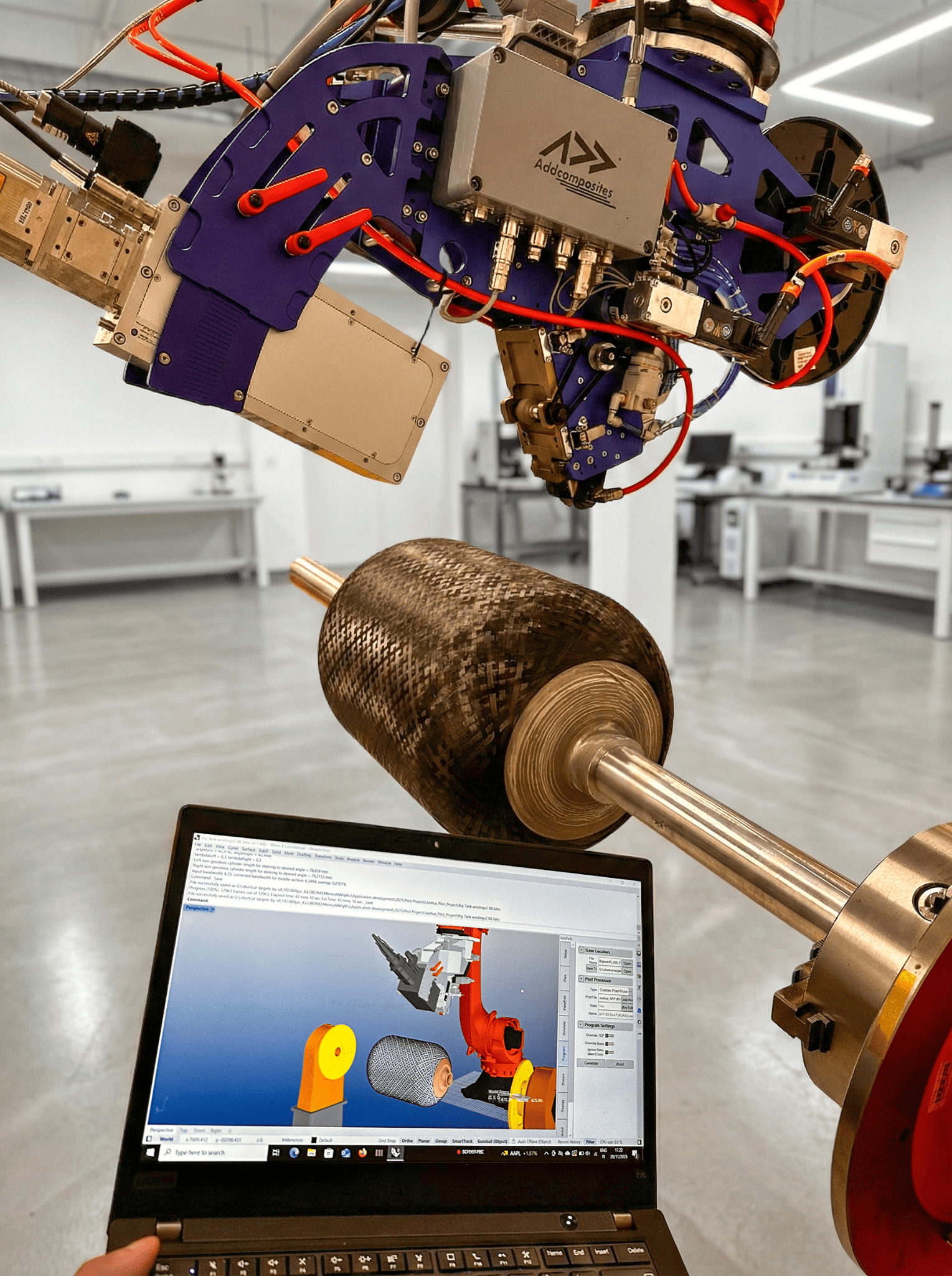
AddPath toolpath simulation displayed on a laptop alongside the AFP head and a wet-wound carbon fiber cylinder — showing the software environment used for path planning, layup simulation, and robot-program generation for winding geometry.
AddPath: path planning for both AFP and winding
Path planning, simulation, material and time estimation, and robot-program generation for both AFP and winding are handled in AddPath.
Why that matters here: the study's whole story is that strength under a biaxial field depends heavily on the layup, namely the ratio of hoop to off-axis plies, the exact off-axis angle, and the symmetry of the stack. A hoop-heavy sequence with tightly specified shallow plies, like the one the authors used, is only as good as your ability to place those angles repeatably. No process "solves" biaxial weakness, because the reduction is physical. But the angle fidelity and repeatability of how the fiber is laid down is a first-order design lever, not a manufacturing afterthought, and being able to wind the shell and lay up the coupons on one programmable platform keeps that lever in the designer's hands across the whole part family.
The complementary lesson is about testing. A study like this is a reminder that qualifying a deep-sea laminate against uniaxial coupons and a generic knockdown factor can leave you holding a smaller margin than the paperwork shows. Designing the layup deliberately and validating the failure criterion against representative biaxial or hydrostatic data is the more defensible path — and it is a path that gets easier when your layup is precise and repeatable to begin with.
Read the Research
Zhou, C.; Tang, Z.; Deng, X.; Gao, Y.; Jiang, H. Strength and
Failure Behavior of Carbon Fiber Composite Laminates Under Biaxial
Compression for Deep-Sea Application.
Journal of Composites Science 2026, 10, 130.
https://doi.org/10.3390/jcs10030130
Open access, published 28 February 2026 by MDPI under
the Creative Commons Attribution (CC BY 4.0) license. © 2026 by the authors.
Affiliations:
Institute of Mechanics, Chinese Academy of Sciences; School of
Engineering Science, University of Chinese Academy of Sciences;
Tianjin Istar-Space Technology Co., Ltd.; and the Department of
Mechanics and Engineering Science, Nanjing University of Science and
Technology.
Learn More
Get in touch to discuss your deep-sea composite manufacturing application →
Contact Us for a ConsultationReferences
- Zhou, C.; Tang, Z.; Deng, X.; Gao, Y.; Jiang, H. Strength and Failure Behavior of Carbon Fiber Composite Laminates Under Biaxial Compression for Deep-Sea Application. Journal of Composites Science 2026, 10, 130. https://doi.org/10.3390/jcs10030130
Addcomposites builds automated composite manufacturing systems — AFP-XS, AFP-X, and ADDX — together with the AddPath and AddWind software platforms. This article is independent editorial commentary on third-party research; it does not represent an endorsement by the study's authors of Addcomposites or its products.
